Size for the steam load. Select for the pressure, temperature and discharge system.
Steam safety-valve selection starts with required relieving capacity, set and operating pressures, temperature, blowdown/reseating behavior and the actual installation—not a boiler label alone.
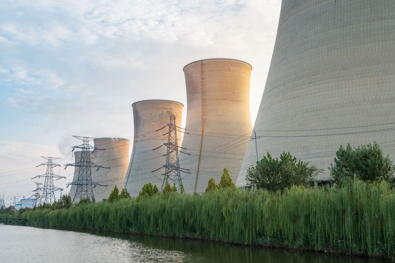
Six inputs shape the valve and installation decision.
Steam capacity
Use the credible relief case and required steam discharge load as the sizing basis; do not infer capacity from nominal size alone.
Set & operating pressure
Confirm the protected-equipment limit, set pressure and normal/maximum operating pressure to establish operating margin.
High-temperature service
Verify relieving temperature against the selected series, materials, spring/bonnet configuration and project requirements.
Blowdown & reseating
Opening, blowdown and reseating requirements affect stable operation and must be reviewed against the selected valve and applicable standard.
Large discharge requirement
Large steam loads may change required area, size and the appropriate direct spring-loaded versus engineered system architecture.
Inlet / outlet conditions
Review inlet losses, discharge piping, backpressure, drainage, reaction/loads and the actual installation conditions that can affect valve performance.
Treat high temperature as a configuration duty, not a separate valve family.
Spring-Loaded Safety Relief Valves
Direct spring-loaded valves are evaluated from required capacity, set pressure, temperature, medium, installation and the actual series limits.
High-Temperature Spring-Loaded configurations
High-temperature arrangements are configurations within the spring-loaded family. Exact temperature, materials and pressure limits must be checked by model/series.
Impulse & Main Safety Valve Systems
For large-discharge/high-pressure steam duties, Main Safety Valves and Impulse Safety Devices may be evaluated as a complete system only within their actual technical scope.
Turn steam/service data into a reviewable selection.
Service data
Collect steam condition, required capacity, operating/set pressures, temperature, backpressure and installation data.
Sizing basis
Establish the applicable calculation method, coefficients/assumptions and required discharge area/capacity.
Architecture
Select the valve/system type, size, connections, materials and high-temperature configuration against the actual series limits.
Compliance review
Check applicable design standard, test requirements and the certification/marking scope required by the project.
Technical submittal
Issue the applicable datasheet, calculation basis, GA/dimensions, deviations, certification evidence and document list.
Keep the performance record connected to the delivered valve.
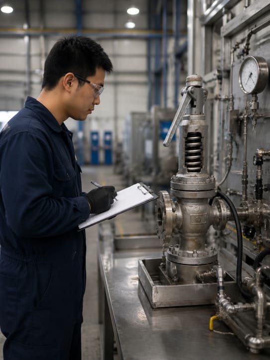
Set pressure & reseating
Verify the required set-pressure and reseating/blowdown-related test scope according to the selected product, applicable standard and order requirements.
Seat leakage
Apply the specified seat-leakage test basis where applicable; do not assume one leakage criterion covers every steam valve or certification scope.
Material / serial records
Maintain applicable material, heat/serial and inspection records at the level required for the supplied product and order.
Technical delivery file
Provide the agreed drawings, material records, test reports and conformity/certification documents applicable to the actual supplied valves.
Designed to, tested in accordance with and certified to are three different claims.
Designed to
The selected design follows stated code/standard requirements within its documented technical basis; this alone is not a certification mark.
Tested in accordance with
A defined test was performed to the referenced method/acceptance scope; this does not automatically establish product certification.
Certified to
The supplied model must fall within the actual certificate/authorization holder, factory, product and pressure/marking scope.
HHSV confirms whether the selected supply requires and falls within the applicable ASME authorization and marking scope.
ASME Section I power-boiler safety valves require the applicable V authorization/marking scope. A UV authorization for Section VIII pressure-vessel pressure relief valves must not be generalized into Section I/V certification. If Section I/V is required, verify the actual certificate scope for the selected supply before quotation or approval.
Steam-service evidence stays project-specific.
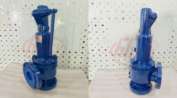
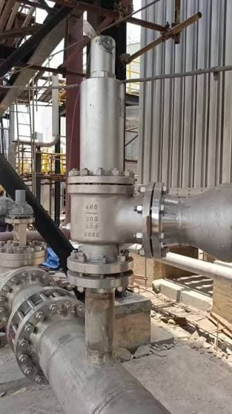
Full-Nozzle Safety Valves with Balanced Bellows
Supplied for steam-pipeline overpressure protection in an industrial thermal system. The full-nozzle configuration addressed discharge demand, while balanced bellows were used to reduce the influence of outlet backpressure.
Exact project pressure, temperature, size and quantity are not generalized beyond the project record.
Engineering & Sizing
Review service data, capacity and calculation basis before selection.
Certifications
Verify certificate holder, model and actual pressure/marking scope.
Quality & Testing
Review inspection, traceability and performance-testing controls.
Projects
Review current supply records without extending one project’s parameters to another.
Send the steam load and installation conditions together.
Include required capacity, operating/set pressures, temperature, backpressure, inlet/outlet connections and piping conditions, required standard/certification, quantity, inspection and document requirements.