HHSV · Steam Overpressure Protection
Impulse & Main Safety Valve Systems
The GA49H-4.0 DN25 impulse safety valve works with the A49H-40 main safety valve to protect steam equipment from overpressure. The impulse valve initiates opening; the main valve provides the steam discharge path. Compare both models below, then send your operating conditions for selection.
One Protection System, Two Valve Functions
One valve initiates opening. The other releases steam.
GA49H-4.0 DN25 is the impulse valve specified for use with A49H-40. When the impulse valve opens, steam passes through the impulse pipe into the main valve’s piston chamber and opens the main valve.
Protected steam system
Steam pressure acts at the impulse valve’s protected-system connection.
GA49H impulse valve
The lever-and-weight impulse valve opens when its set pressure is reached.
Impulse pipe
Steam enters the main valve’s piston chamber through the impulse pipe.
A49H-40 main valve
Steam pressure pushes the piston down and opens the main valve.
Discharge & recovery
The main valve discharges steam and closes automatically after the impulse valve closes.
Opening & Reseating Logic
From impulse-valve opening to main-valve reseating.
The GA49H-4.0 DN25 uses a lever and weight to balance the force on its disc. The A49H-40 uses steam from the impulse pipe to actuate its piston. Confirm set pressure, reseating and response requirements for the selected pair.
Normal condition
The impulse valve remains sealed while its lever and weight balance the pressure force on the disc.
Set condition reached
The impulse valve opens when pressure reaches its specified setting.
Main opening
Steam enters the A49H-40 piston chamber, pushes the piston down and opens the main valve.
Steam discharge
The A49H-40 provides the main steam discharge path. Select its size using the required relieving capacity.
Pressure recovery
As system pressure falls, the impulse valve returns to its closing condition.
Main reseating
The A49H-40 disc closes automatically after the impulse valve closes. Verify reseating against the agreed test criteria.
Models & Specifications
Compare the impulse valve and main valve.
Both models are listed for steam service at PN40 and temperatures up to 425°C, with flanged connections. Their sizes and operating roles differ. Open each product page for its detailed description and available dimensions.
01 · IMPULSE VALVE
GA49H-4.0 DN25
Impulse Safety Valve
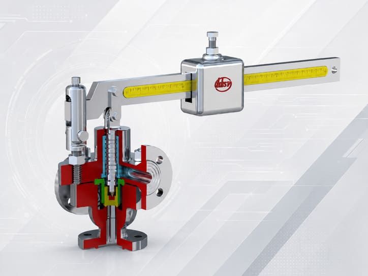
- Medium
- Steam
- Nominal size
- DN25
- Pressure rating
- PN40
- Temperature
- ≤425°C
- Connections
- Flanged
- Operating principle
- Lever and weight
02 · MAIN VALVE
A49H-40
Main Safety Valve
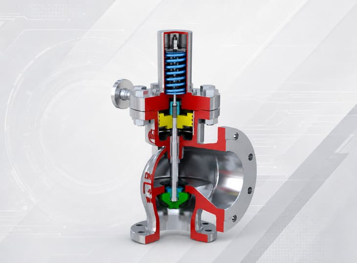
- Medium
- Steam
- Nominal sizes
- DN150 / DN200 / DN250
- Pressure rating
- PN40 (4.0 MPa)
- Temperature
- ≤425°C
- Connections
- Flanged
- Operating principle
- Impulse steam / piston
Why Impulse + Main
A small impulse valve controls a larger steam discharge path.
The GA49H-4.0 DN25 supplies the opening impulse to the A49H-40, which is listed in DN150, DN200 and DN250. Select the main valve for the required steam capacity, then confirm the impulse setting and the piping arrangement for the pair.
Architecture Comparison
Compare valve operating principles for your application.
Start with the protected equipment and relief duty. Then compare how each valve family opens, the available model ratings and the installation requirements.
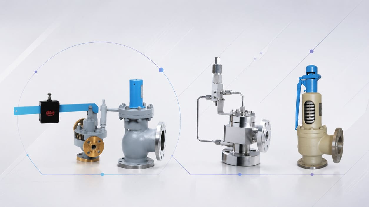
Impulse & Main
A GA49H-4.0 DN25 lever-and-weight impulse valve sends steam to the A49H-40 piston chamber to open the main valve.
Pilot-Operated
The A46 family uses a pilot and main-valve arrangement. Select the pressure group and configuration from the applicable A46 product data.
Direct Spring-Loaded
Process pressure acts against the spring force on the disc. Compare the listed lift, enclosure, connection and pressure options for each model.
Installation & System Layout
Plan the impulse connection, main valve and discharge piping together.
Use the selected valve drawings and approved system layout to define orientation, impulse piping and access. The product instructions also identify support, drainage and lever-position requirements that must be included in the installation review.
Protected steam connection
Confirm the impulse pressure take-off and instrument locations against the product instructions and system drawing.
Impulse / control line
Clean the piping before installation. Confirm impulse-line routing and its connection to the main valve’s piston chamber.
Main valve inlet
The A49H-40 instructions specify vertical installation at the highest point of the equipment, with support for discharge reaction forces.
Discharge piping
Provide separate supports for the discharge pipe so its weight and flange loads are not carried by the main valve.
Drainage / condensate
Provide drainage at the lowest point of the steam discharge pipe, as specified in the A49H-40 installation instructions.
Access & maintenance
Install the impulse valve vertically, keep its lever level and retain access for setting, inspection and maintenance.
Sizing & System Design
Match main-valve capacity and impulse operation to the steam duty.
The A49H-40 main valve must meet the required steam relieving duty. The GA49H-4.0 DN25 impulse valve and its connecting pipe must provide the specified opening action. Review both against the project’s pressure, temperature, discharge and code requirements.
Credible steam relieving case
Define the overpressure scenario and required steam mass flow. This establishes the main-valve duty.
Operating / set pressure
Provide normal pressure, set pressure and the permitted accumulation/overpressure basis.
Relieving temperature
Both product records list a maximum temperature of 425°C. Confirm the selected materials and pressure-temperature suitability.
Main-valve capacity
Verify A49H-40 capacity using the applicable product data and sizing calculation. Nominal diameter alone does not establish capacity.
Impulse setting / logic
Confirm the GA49H-4.0 DN25 set-pressure requirement and the operating sequence for the paired main valve.
Backpressure / discharge system
Provide outlet pressure and discharge-piping details for review of the main valve’s relieving performance.
System pressure losses
Review inlet, impulse/control and discharge-path effects against the governing design basis.
Code / owner basis
State the applicable boiler/pressure system code, project specification, required marking and witness requirements.
Materials, Connections & Dimensions
Match the selected valve to its materials and connection drawing.
Both models have flanged connections. The A49H-40 product page includes a connection-dimension table for DN150, DN200 and DN250. Confirm the ordered materials, mating flanges and installation dimensions in the approved documents.
Material / MTC
Confirm body, disc, seat and other specified materials for each valve against the order and material records.
Connection details
Check inlet and outlet sizes, flange dimensions, facing, drilling and the impulse connection for the selected configuration.
Dimensions / weights
Use the selected model’s dimensional drawing for overall size, installation space and maintenance access.
System interface
Match the impulse pipe, pressure take-off, drainage and valve-to-valve connections to the approved system drawing.
Standards, Certification & Compliance
Confirm the standards and approval scope for the selected valve pair.
State the required product, installation and test standards in your enquiry. The quotation and technical documents should identify the applicable requirements for each valve and the complete system, including any requested certification or marking.
Product design basis
Confirm the design and manufacturing standard for the ordered A49H-40 and GA49H-4.0 DN25 configuration.
Project test requirements
Specify the required test methods, acceptance criteria and document references in the enquiry and inspection plan.
Boiler applications
Identify the governing boiler code and the product authorization or marking required for the installation.
Pressure-vessel applications
Confirm the applicable vessel code, relief requirements and certification scope for the selected product.
Owner / EPC requirements
Include the owner’s material, inspection, witness, documentation and local regulatory requirements in the agreed scope.
Certificate scope
Check the certificate holder, manufacturing location, product range, validity and permitted marking against the order.
Designed to
The stated standard forms the design or sizing basis for the selected valve and system configuration.
Tested in accordance with
The stated test procedure and acceptance criteria apply to the supplied valves and recorded inspection results.
Certified to
The certificate or authorization covers the supplied product, certificate holder, factory and required marking.
Inspection & Performance Testing
Verify impulse operation and main-valve response.
Agree the inspection and test scope for the valve pair, including set pressure, opening, reseating and leakage checks. Specify any steam test, combined operation test or witness requirement in the order.
Pressure boundary
Check the pressure-boundary integrity of both valves using the agreed procedure and acceptance criteria.
Impulse-valve setting
Verify GA49H-4.0 DN25 opening behaviour and the specified pressure setting.
Main-valve opening
Verify A49H-40 opening when steam is admitted through the impulse connection.
Reseating sequence
Record impulse-valve closing and the resulting main-valve reseating against the specified criteria.
Seat leakage
Apply the agreed seat-leakage test method and record the results for the supplied configuration.
Integrated system function
Where included in the order, test the paired valves and impulse connection together and record the observed sequence.
Pre-Shipment Visual Verification
Check both valve identities and connection interfaces before shipment.
Shipment photographs can show the supplied A49H-40 main valve, GA49H-4.0 DN25 impulse valve, nameplates, flanges and accessories. Review them alongside the approved drawings, packing details and inspection records.
Dimensions & Technical Documentation
Bring the two valve records and system drawing into one document package.
Agree the required datasheets, drawings, calculations and inspection records at the quotation stage. Each document should identify the ordered model and configuration.
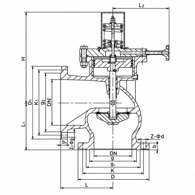
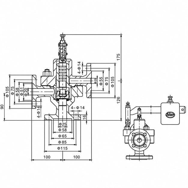
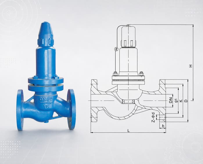
Reference drawings. Confirm the ordered size and connections against the approved project drawing.
A49H-40 datasheet
Selected size, set/service basis, main-valve configuration, materials and applicable options.
GA49H-4.0 DN25 datasheet
Trigger/set basis, configuration, interfaces, materials and model-specific operating data.
System sizing calculation
Credible steam case, required capacity, pressure/temperature assumptions and selected main-valve duty.
GA / dimensional drawings
Selected valve dimensions, orientation, connection interfaces and required installation clearances.
System / impulse schematic
Approved impulse/control path, sensing point, drains and relationship between the two devices.
Material records
Material certificates and any specified inspection or traceability records for the agreed scope.
Test / witness reports
Pressure, set/trigger, main opening, reseating, leakage and integrated function records as applicable.
Approval & release records
Applicable certificates, approved document revisions and the agreed final inspection and release records.
Typical Steam Application Routes
Select the valve pair for the equipment and steam duty.
The product descriptions cover power plant boilers, pressure vessels, and pressure and temperature reducing equipment. Confirm capacity, operating conditions and installation requirements for each application.
Power-station steam systems
Review the required steam relief duty, discharge system and operating conditions for the selected valve pair.
Boiler steam protection
Compare the boiler’s overpressure protection requirements with the valve ratings and applicable approval scope.
Steam pressure vessels
Confirm the protected vessel’s pressure limit, required relief capacity and connection arrangement.
Steam pressure-reduction systems
Use the pressure and temperature reducing equipment’s relief scenario to establish the required steam discharge duty.
Main steam discharge
Compare A49H-40 DN150, DN200 and DN250 using verified capacity data and the required relieving conditions.
OEM / engineered packages
Coordinate the main valve, impulse valve, connecting pipe and inspection documents with the package layout.
Project Requirements
Define the application, valve pair and delivery documents.
Send the available project specification and equipment information with your enquiry. These details help define the selected models, inspection scope and required documents before an order is placed.
Application & region
Identify the protected equipment, installation location and governing project requirements.
Relieving basis
Steam duty, set pressure, temperature, required capacity and discharge/backpressure conditions.
Requested valve pair
Specify A49H-40 main-valve size, GA49H-4.0 DN25 impulse valve, materials and quantities.
Delivery Documentation
List required drawings, calculations, material certificates, test reports and delivery milestones.
FAQ
Impulse/main system questions
Key questions about model selection, impulse operation and the information needed for an enquiry.
Which two models form the impulse/main pair?
The GA49H-4.0 DN25 Impulse Safety Valve is specified for use with the A49H-40 Main Safety Valve. The impulse valve initiates opening, and the main valve provides the steam discharge path.
What are the listed sizes and operating ratings?
GA49H-4.0 DN25 is listed at DN25 and PN40. A49H-40 is listed at DN150–250 and PN40 (4.0 MPa). Both product records specify steam, temperatures up to 425°C and flanged connections. Confirm suitability for the ordered service conditions.
How does the impulse valve open the main valve?
The GA49H impulse valve uses a lever and weight to balance the pressure force on its disc. When it opens, steam passes through the impulse pipe into the A49H-40 piston chamber, pushes the piston down and opens the main valve. The main valve closes automatically after the impulse valve closes.
How does this compare with an A46 pilot-operated valve?
The GA49H/A49H pair uses a separate lever-and-weight impulse valve and a steam-actuated main-valve piston. The A46 family uses its own pilot and main-valve arrangement. Compare each family’s product data with the required duty.
Can the main valve be selected from DN alone?
No. Required steam capacity depends on the relieving scenario and operating conditions. Confirm the selected A49H-40 capacity with the applicable data and calculation, then check impulse operation and discharge conditions.
Which standards and certificates apply?
Confirm the required design, test and installation standards for the selected valve pair during the enquiry. Any certificate or authorization must cover the supplied product and required marking. Include the governing boiler or pressure-vessel requirements in your specification.
What information is needed for a quotation?
Send the protected equipment, required steam capacity, operating and set pressure, temperature, discharge conditions, available drawings, connection and material requirements, quantity and delivery target. Include the required code, inspection and documentation scope.
Related Safety Valve Families
Compare the valve family with the protection duty.
Spring-Loaded Safety Relief Valves
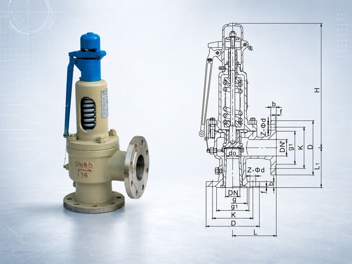
Spring-loaded safety valves with model-specific lift, enclosure, connection and pressure options.
Pilot-Operated Safety Relief Valves
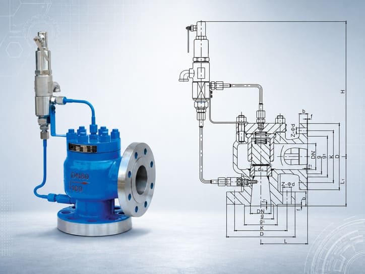
A46 pilot-operated safety valves with their own pilot arrangement and model-specific pressure groups.
Safety Reflux Valves
AH42F and AHN42F-P18 valves for liquid-phase return-line relief at LPG station pump outlets.
All Safety Valves
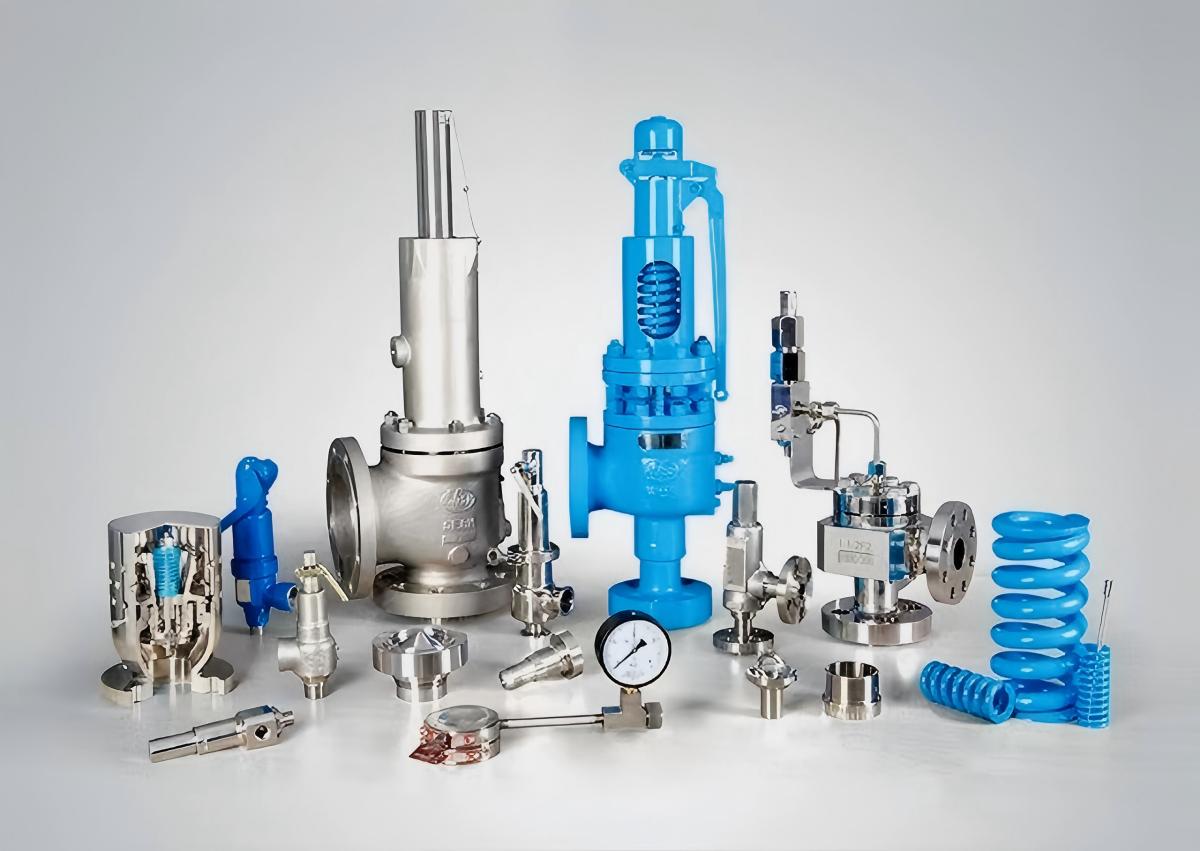
Return to the family map and compare selection routes across HHSV’s safety-valve portfolio.
Request a Quote
Send your steam duty for valve-pair selection.
Share the protected equipment, required steam capacity, operating and set pressure, temperature, discharge conditions, drawings, connection requirements and quantity. Include the applicable code, inspection documents and delivery target.