
Back-Flow Safety Valves
Safety Reflux Valves for LPG Pump Return Lines
HHSV AH42F and AHN42F-P18 safety reflux valves provide overpressure protection for liquid-phase return lines at LPG station pump outlets. Compare the two products below, then send the operating conditions and piping arrangement for selection.
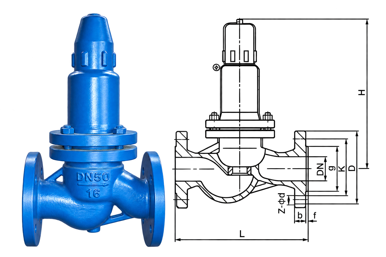
AHN42F-P18 Parallel Safety Reflux Valve · Flanged configuration
Table of Contents
Product Specifications
Compare sizes, pressure ratings and temperature limits.
The ranges below belong to the named product. Pressure ratings are not opening-pressure settings; the selected materials and operating temperature determine the permissible service conditions.
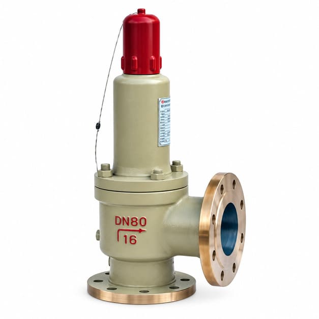
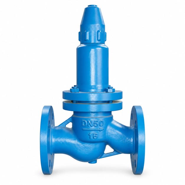
AHN42F-P18 Parallel Safety Reflux Valve
DN40–DN150 · Parallel safety reflux configuration
Swipe to compare the two models.
| Specification | AH42F | AHN42F-P18 |
|---|---|---|
| Model | AH42F-16/25/40-C | AHN42F-P18 |
| Nominal size | Inlet: DN20–DN350 Outlet: DN25–DN500 | DN40–DN150 |
| Pressure rating | PN16 / PN25 / PN40 1.6 / 2.5 / 4.0 MPa | Class 150–300 |
| Temperature range | −29 °C to +80 °C | −196 °C to +200 °C |
| Connections | Flanged | Flanged |
| Application | Liquid-phase return lines at LPG station pump outlets | Liquid-phase return lines at LPG station pump outlets |
Pressure ratings and temperature limits are model-specific. Confirm the selected material, pressure–temperature rating, set pressure and service conditions for each order.
How Safety Reflux Works
Relieve excess pressure through the liquid return line.
The safety reflux valve connects to the liquid return line at the LPG pump outlet. When the specified pressure is exceeded, the valve opens automatically and allows liquid to return through the designated route. The selected valve, opening pressure and return destination must match the piping design.
Pressure relief through a return branch
01
Normal operation
The pump supplies the process through its normal delivery line.
02
Pressure rises
Pressure reaches the specified opening condition for the safety reflux valve.
03
Liquid returns
The valve opens automatically, allowing liquid to flow through the designated return line.
04
Pressure recovers
The AH42F closes automatically as pressure falls to the specified setting.
Selection Basis
Provide the pump, liquid and return-line conditions.
Selection starts with the protected pressure, required return capacity and pressure at the return destination. Include the pump data and piping sketch so the valve rating, size and opening-pressure requirement can be reviewed together.
State operating pressure and the required set pressure.
State pressure at the return destination and in the return line.
Provide the required relief or return-flow duty.
State the liquid and its operating temperature.
Confirm inlet/outlet sizes, flange standard and rating.
System function
Describe the pump-outlet overpressure condition that the liquid return line must relieve.
Inlet & return pressure
Give normal and maximum pressure at the protected connection, return-line pressure and the required opening pressure.
Required return flow
Provide the required liquid return flow or the pump duty data used to establish it.
Medium & properties
Give liquid composition, density, viscosity and relevant corrosion or phase-change information.
Temperature
State minimum, normal and maximum operating temperatures for the selected liquid service.
Piping & orientation
Provide line sizes, flange details, return destination and a P&ID or piping sketch.
Material requirement
State the required body and sealing materials, corrosion allowance and material documentation.
Inspection & documents
Identify required test reports, inspection or witness points, drawings, quantity and delivery date.
Construction & Connections
Match the valve interfaces to the selected product drawing.
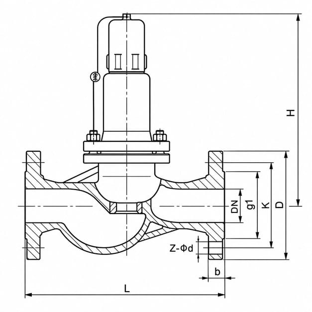
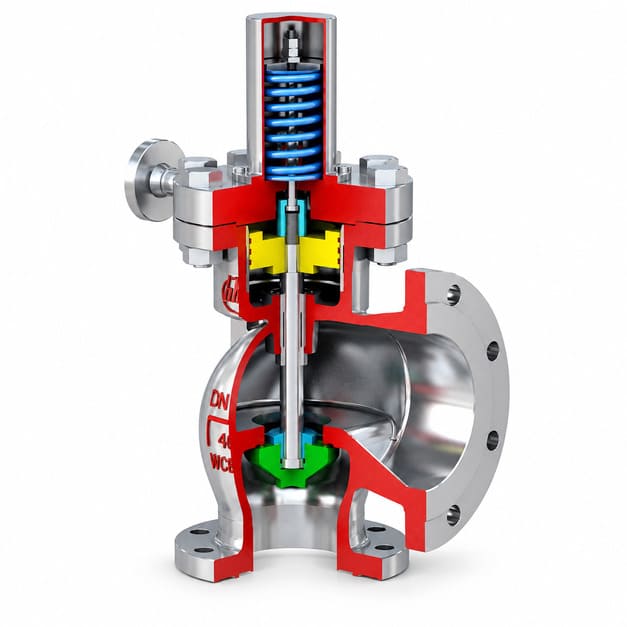
Product photographs help identify the general configuration. Use the model-specific connection drawing and supplied valve documentation for port sizes, materials, overall dimensions and installation requirements.
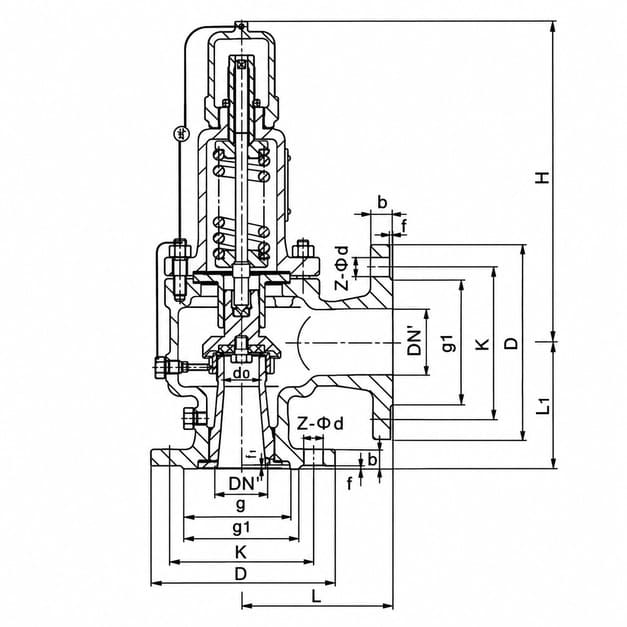
AH42F section and connection layout
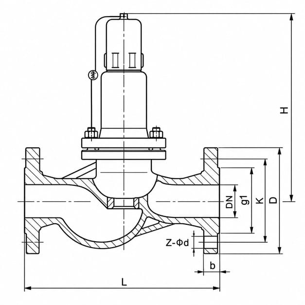
AHN42F-P18 section and connection layout
Body & flow path
Identify the protected-line connection and return-line connection on the selected product drawing.
Opening-pressure setting
State the required opening pressure in the enquiry and confirm the setting and test record for the supplied valve.
Model & configuration
Match AH42F-16/25/40-C or AHN42F-P18 to its own dimensions and ordered pressure rating.
Seat & sealing
Specify the seat-leakage acceptance requirement and confirm the sealing materials for the liquid service.
Flanged interfaces
Match flange size, facing, drilling and rating to both mating connections.
Nameplate & identification
Check the model, rating and traceability information against the order and supplied documentation.
Installation Arrangement
Connect the protected line and return destination as designed.
The P&ID and selected valve drawing should identify the pump outlet, safety reflux branch and return destination. Confirm port identification, allowable orientation, supports and maintenance access before installation.
A
P&ID
Identify the pump outlet, relief branch and destination of the returning liquid.
B
Port identification
Match the inlet and return connections, including any body markings, to the approved drawing.
C
Orientation
Follow the installation instructions for the selected AH42F or AHN42F-P18 configuration.
D
Access
Provide space for inspection, nameplate reading, removal and maintenance.
Materials & Connections
Specify materials and flanges for the selected model.
The material specification must suit the liquid, operating temperature and pressure. Confirm body, internal and sealing materials together with flange details in the quotation and product documentation.
Body / trim
Match the specified materials to the liquid and pressure-temperature conditions.
Sealing materials
Confirm compatibility with the liquid, temperature range and leakage requirement.
Flange details
Confirm nominal size, standard, facing, bolt drilling and pressure-temperature rating.
Model-specific temperature
AH42F is listed at −29°C to +80°C. AHN42F-P18 is listed at −196°C to +200°C, subject to the materials and configuration supplied.
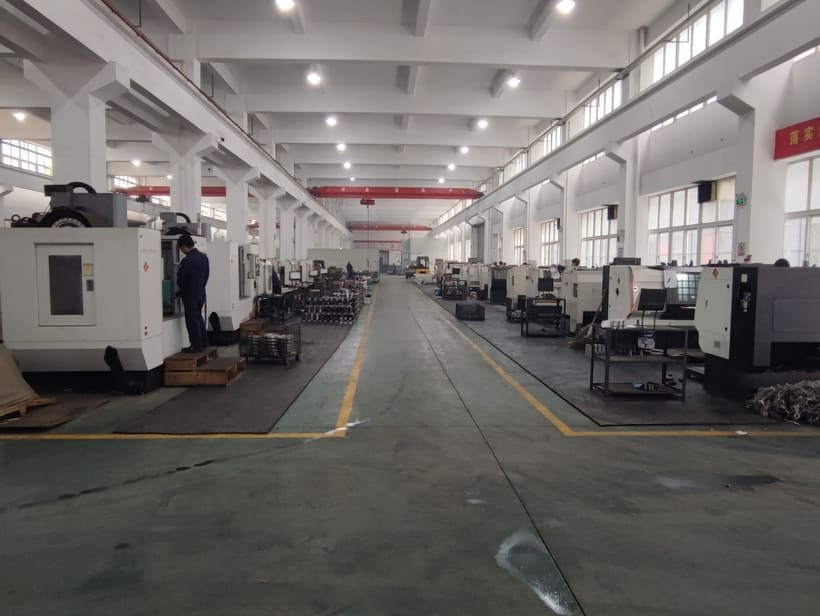
CNC machining workshop
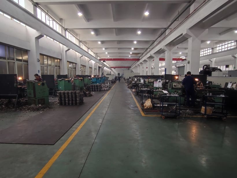
Machining workshop
Standards & Compliance
Define the standards and documentation for your order.
The quotation should identify the applicable design basis, pressure and leakage tests, functional checks and document requirements. Certification or authorization is confirmed against the exact product and scope requested.
Designed to
The stated standard forms the design, sizing or dimensional basis for the selected valve.
Tested in accordance with
The supplied valve is tested using the stated method and acceptance criteria for the agreed scope.
Certified to
The certificate or authorization must cover the supplied product, certificate holder and manufacturing location.
Test requirements
State the required pressure, leakage and functional test methods in the purchase specification.
Certification scope
Request the documents applicable to the selected model, rating and manufacturing scope.
Project specification
Include the owner or EPC requirements for piping interfaces, materials, inspection and documentation.
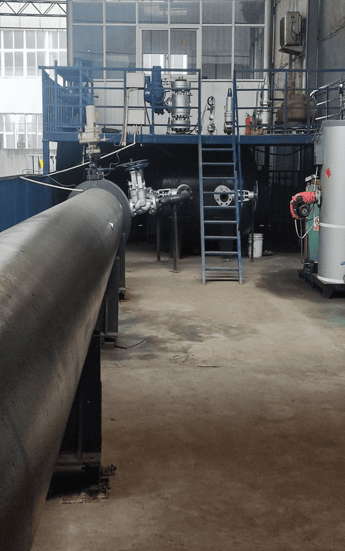
Performance test facility
Inspection & Testing
Record the pressure-relief and sealing checks for the supplied valve.
The inspection plan connects the ordered valve, opening-pressure requirement, liquid return duty, sealing acceptance and connection dimensions to the required test records.
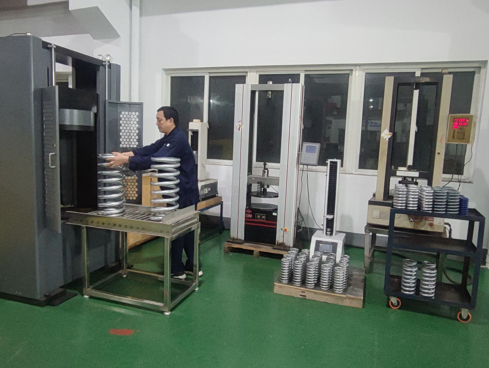
Spring stiffness testing area · HHSV facility
Pressure boundary
Record the pressure-boundary test method, test pressure and acceptance result.
Functional response
Check the opening response and the applicable closing or reseating criteria for the selected model.
Seat leakage
Check seat leakage using the test conditions and acceptance criteria agreed for the order.
Flow / capacity check
Where required, verify liquid return capacity against the specified duty and test basis.
Dimensional inspection
Check the connection dimensions, flange interfaces and overall envelope against the approved drawing.
Material traceability
Provide material and traceability records for the scope agreed in the purchase order.
Pre-Shipment Visual Verification
Check the ordered model and connection arrangement before shipment.
Shipment photographs can show the supplied valve, nameplate, flange interfaces and overall configuration. Review them alongside the approved drawing, packing details and inspection records.

- 1Supplied valve & model
Match the supplied valve and model designation to the order documents and approved drawing.
- 2Nameplate & settings
Verify the nameplate identification and stated settings against the order documents and inspection records.
- 3Flange interfaces
Compare connection sizes and flange details with the approved drawing, and check the flange faces for visible damage.
- 4Overall configuration
Compare the complete valve and connection arrangement with the approved drawing. Review the packing details and inspection records.
Dimensions & Technical Documentation
The approved GA controls installation dimensions, interfaces and flow direction.
Use the AH42F or AHN42F-P18 connection dimension table to begin layout review. The approved drawing for the ordered size and rating confirms the final dimensions and installation arrangement.
Product datasheet
Selected model, liquid service, opening pressure, return duty, temperature, materials and connections.
GA / dimension drawing
Connection sizes, flange details, center or face dimensions and overall envelope.
BOM / material records
Body, internal and sealing materials, with material records as specified.
Functional test report
Opening-pressure and applicable closing or reseating acceptance results for the supplied model.
Pressure test report
Pressure-boundary test procedure, test pressure and recorded result.
QAP / ITP
Inspection stages, hold or witness points and third-party requirements when specified.
Compliance statement
The applicable design, test and project requirements identified for the exact supply.
MTC / final dossier
An agreed index of drawings, material records, inspection reports and shipment documents.
LPG Return-Line Applications
Plan the return route around the pump and connected equipment.
Both products are described for liquid-phase return lines at LPG station pump outlets. The following points help define that arrangement before selecting the valve size and rating.
Pump-outlet relief branch
Identify the protected pump-outlet connection and the pressure condition that requires relief.
Return destination
Show where the liquid returns and provide the pressure conditions at that destination.
Required liquid flow
Use the pump duty and relief scenario to establish the return-flow requirement.
Liquid temperature
Match operating temperatures and material requirements to the selected product range.
Piping connections
Compare the inlet and outlet dimensions with the return-line piping and mating flanges.
Equipment access
Allow space for supports, inspection, removal and maintenance in the skid or station layout.
Project Submittal Package
Keep the selection, inspection and delivery documents together.
A clear submittal links the liquid return duty to the selected valve and the documents required by the purchaser. Agree the drawing and inspection deliverables during quotation.
System context
Pump operating data, liquid properties, pressure conditions and the intended return route.
Selected valve
AH42F or AHN42F-P18 model, size, rating, materials and connection details.
Functional verification
Agreed pressure, functional and seat-leakage checks with any inspection witness points.
Delivery Documentation
Approved drawings, material records, test reports and the required shipment documents.
FAQ
Safety Reflux Valve FAQs
Answers to common questions about AH42F and AHN42F-P18 selection.
What are AH42F and AHN42F-P18 used for?
Both products are described for overpressure protection of liquid-phase return lines at LPG station pump outlets. They open automatically at the specified pressure condition to allow liquid to return through the designated line.
How do the two product ranges differ?
AH42F-16/25/40-C is listed with PN16/25/40 ratings, inlet DN20–DN350, outlet DN25–DN500 and −29°C to +80°C. AHN42F-P18 is listed with DN40–DN150, Class 150–300 and −196°C to +200°C. Confirm materials, connection details and the permissible operating conditions for the selected configuration.
Does the pressure rating tell me the opening pressure?
The PN or Class designation identifies the pressure rating. Specify the required opening pressure separately, together with operating pressure, return-line pressure and temperature.
Does a safety reflux valve provide a check-valve function?
The stated function of these products is pressure relief through a liquid return line. A reverse-flow shutoff or check-valve requirement needs its own specified performance and supporting product documentation.
Does the name establish balanced-bellows performance?
The safety reflux function does not by itself establish a balanced-bellows construction or a backpressure-compensation capability. Use the selected model drawing and performance data for those requirements.
What determines the installation arrangement?
Use the selected model drawing and installation instructions with the approved P&ID. Confirm the protected connection, return destination, port sizes, flange details, orientation and maintenance access.
What should I send for quotation?
Send the product or duty requested, liquid composition, operating and opening pressures, return-line pressure, required return capacity, temperature, line sizes, flange details, materials, quantity and delivery target. A pump datasheet and piping sketch are useful when selection is still open.
Related Safety Valve Families
Compare the system function before selecting the valve family.
Spring-Loaded Safety Relief Valves
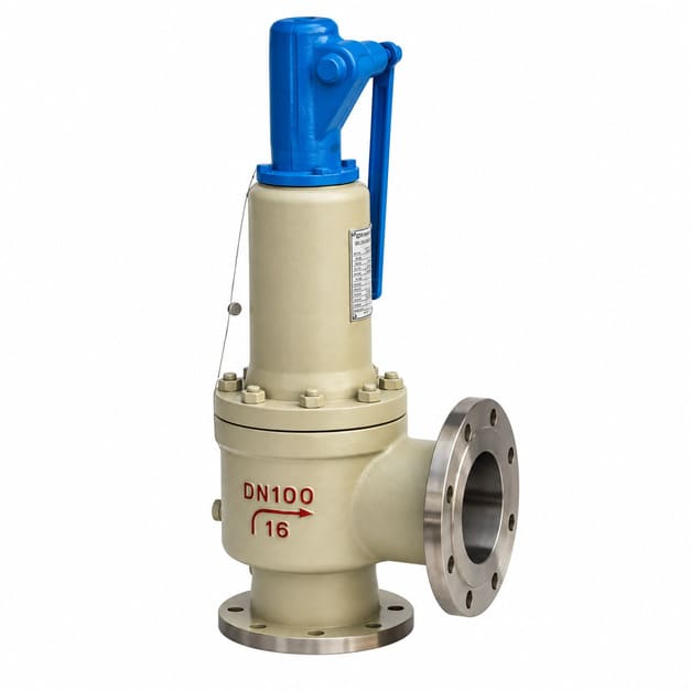
Spring-loaded safety valves for pressure-relief duties. Compare the selected model, medium and operating range.
Pilot-Operated Safety Relief Valves
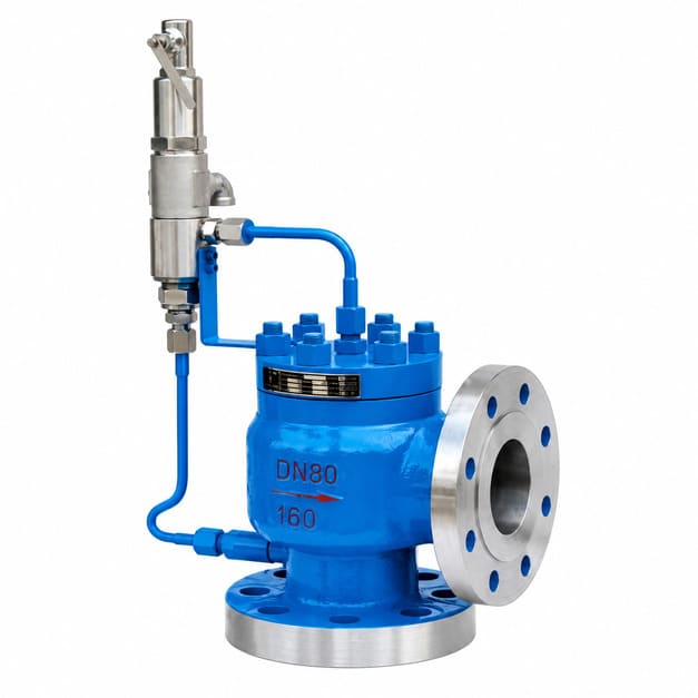
A46 pilot-operated safety valves use a pilot and main-valve arrangement for the specified pressure-relief duty.
Impulse & Main Safety Valve Systems
A49H-40 main safety valves and GA49H-4.0 DN25 impulse safety valves for their specified system duties.
All Safety Valves
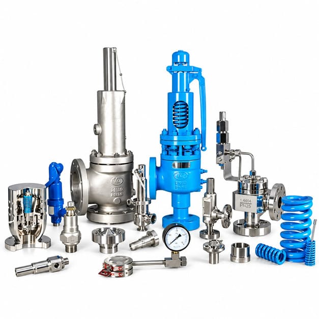
Return to the product-family map and select by function.
Request a Quote
Send your pump and liquid return-line requirements.
Share the liquid, operating and opening pressures, return-line pressure, required flow, temperature, connections and quantity. Include a pump datasheet or piping sketch when available, plus the inspection documents and delivery date you need.