
Vacuum & Breather Valves
Protect tanks and equipment with engineered vacuum and breathing capacity.
HHSV offers HFA72W Vacuum Negative Pressure Safety Valves and HFHX Breather Valves for low-pressure equipment and tank protection. HFA72W supports negative-pressure protection, while HFHX is selected for inbreathing and outbreathing duty. HHSV reviews the equipment pressure limits, flow cases, materials, connections and applicable venting basis for each application.
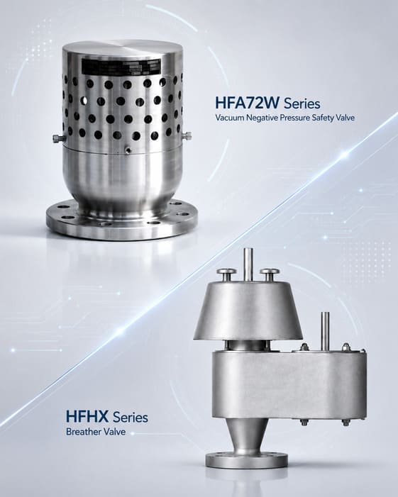
HFA72W
1/2–10 in
Vacuum negative-pressure safety valve · Gas · Class 150 · ≤200°C
Outbreathing
Pressure direction outward
Relieve tank breathing flow when internal pressure rises
HFHX
2–12 in
Breather valve · Gas · Class 150 · ≤200°C
Inbreathing
Pressure direction inward
Protect against excessive vacuum / negative internal pressure
Table of Contents
Pressure Direction Matters
Positive-pressure relief, vacuum protection and tank breathing solve different pressure problems.
A conventional positive-pressure safety relief valve opens to discharge process fluid when internal pressure rises above its set condition. Vacuum protection acts in the opposite pressure direction: it provides an allowed inward gas path when internal pressure falls too far below external/reference pressure. Tank breathing can require both outbreathing and inbreathing capacity as liquid level and vapor temperature change.
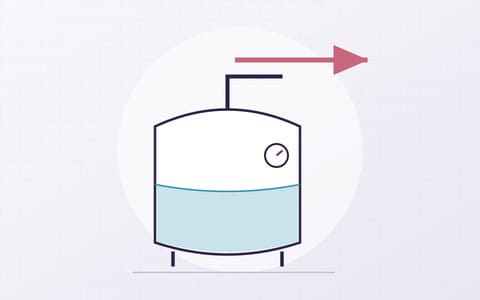
Positive-pressure safety relief
Rising internal pressure requires a suitable outward relief path. Select that function separately from HFA72W vacuum protection.
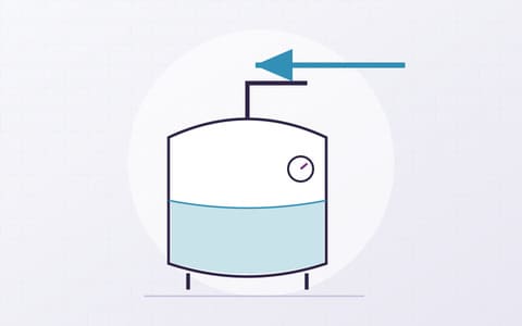
Negative-pressure protection
At the specified negative-pressure condition, an inward air path opens to help protect the vessel against excessive vacuum.
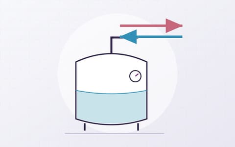
Tank breathing
Normal filling, emptying and thermal expansion/contraction can create outbreathing and inbreathing duties that must be sized separately from emergency overpressure relief.
Breathing Flow Map
Size the direction and the duty - not just the tank nozzle.
Compare the inward and outward flow duties created by tank operation. HFA72W provides the air-admission function for vacuum protection. Any outward venting duty needs its own selected device, settings and capacity data.
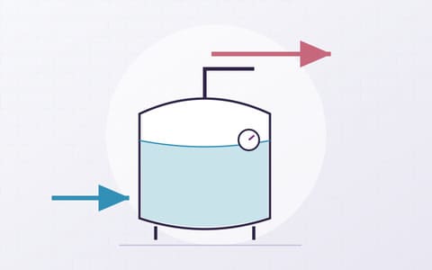
A
Liquid filling / heating
Vapor space is compressed or warmed; internal pressure tends to rise.
B
Outbreathing →
Required vapor/gas flow leaves the tank through the approved breathing route.
C
← Inbreathing
Liquid withdrawal or cooling can create vacuum; allowed gas enters to limit negative pressure.
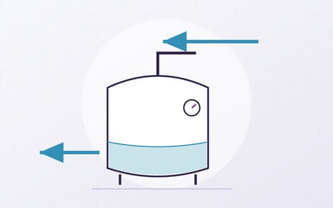
D
Liquid withdrawal / cooling
Vapor space expands or contracts thermally; internal pressure tends to fall.
HFA72W-10-P/R · Negative-Pressure Protection
Protect the equipment when internal pressure falls below the allowed vacuum condition.
HFA72W-10-P/R opens automatically to admit air when vessel pressure reaches the specified negative-pressure condition. The valve closes as pressure returns to the allowable range. Review the required air flow and opening condition for the selected size and service.
01
Normal pressure
Equipment pressure remains above the selected vacuum-opening condition.
02
Vacuum develops
Withdrawal, cooling, condensation or another scenario reduces internal pressure.
03
Inward path opens
At the specified negative-pressure condition, air enters the protected vessel.
04
Pressure recovers
The differential reduces and the valve returns toward its normal seated condition.
Tank Breathing · System Requirements
Breathing demand changes with liquid movement and thermal expansion or contraction.
Tank breathing can require inward and outward gas flow as liquid level and temperature change. Define both duties and the equipment pressure limits before selecting the vent arrangement. HFA72W addresses vacuum protection through air admission; an outward breathing duty needs separate review.
Outbreathing duty
Evaluate filling rate, thermal expansion, vapor generation and any normal vent-header pressure. Required outward capacity is direction-specific.
Inbreathing duty
Evaluate liquid withdrawal, cooling/condensation and blanketing-gas behavior. Required inward capacity is direction-specific.
Set conditions
Positive and vacuum opening conditions must protect the tank without conflicting with normal operating/blanketing pressure.
Capacity / pressure loss
Specify the required flow in each direction and the available pressure differential. Select the connection size using the chosen device’s flow data.
Product Specifications & Selection Inputs
Review the HFA72W range and the tank’s breathing requirements.
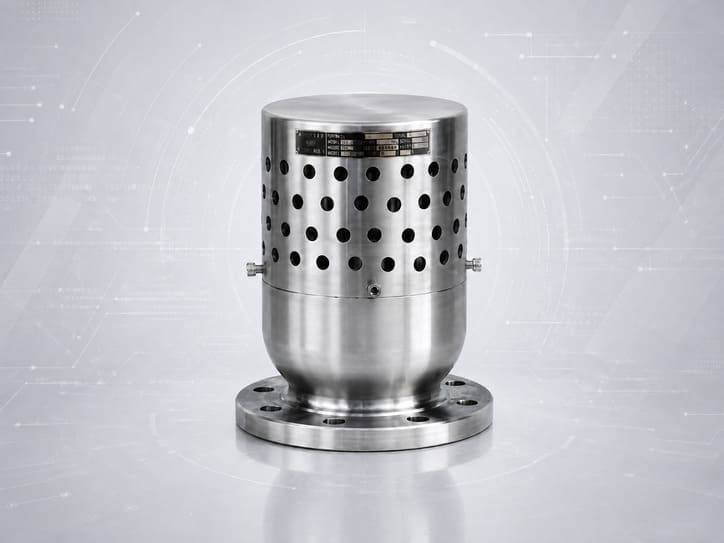
The HFA72W-10-P/R product range is shown below. Vacuum opening conditions and air-admission capacity depend on the selected configuration. Define any separate tank-breathing duty from the vessel pressure limits and operating flow cases.
HFA72W-10-P/R
Vacuum Negative Pressure Safety Valve
Medium
Air / Corrosive Media
Size
DN15–DN200
Nominal Pressure
1.0 MPa · PN10
Temperature
≤200°C
Connection
Flanged
Vacuum Opening & Flow
Confirm for selected duty
Confirm the selected valve’s materials, opening condition, air-admission capacity, flange details and dimensions in the product documents.
Tank-Breathing Requirements
Define the duty before choosing a vent device.
Gas / Vapor
Composition & Compatibility
Flow Cases
Filling, Emptying & Thermal
Pressure / Vacuum Limits
Equipment Design Limits
Temperature
Operating & Ambient
Venting Basis
Project Requirements
Flow Capacity
Review Each Direction
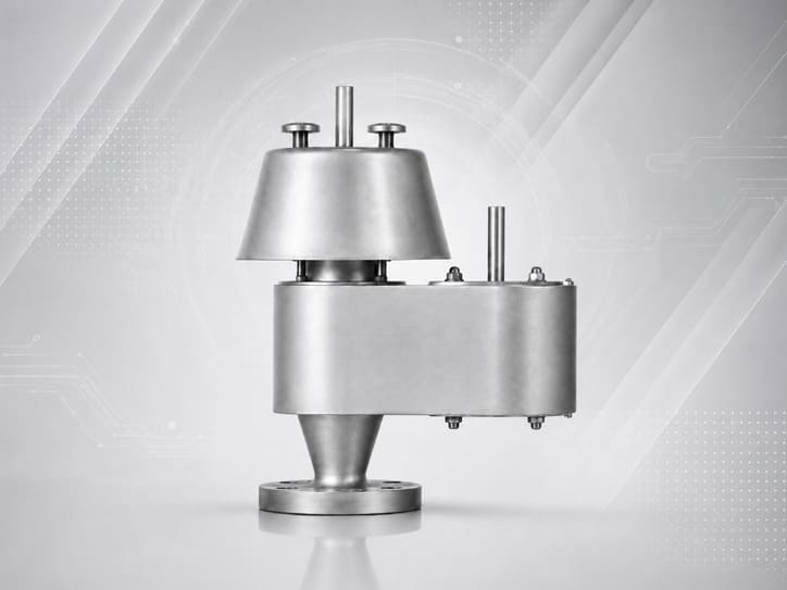
Breather arrangement shown for function reference. Final device selection requires confirmed product data, opening settings and capacity in each required direction.
HFA72W-10-P/R Engineering Data
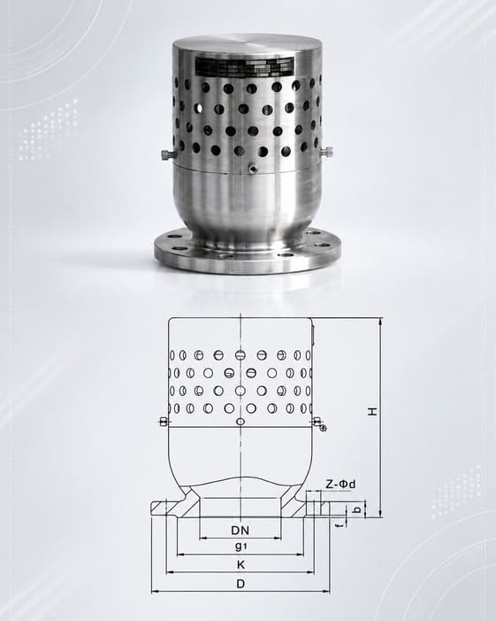
HFA72W-10-P/R Connection Dimensions
Application and dimensional reference for the HFA72W-10-P/R vacuum safety valve, DN15–DN200.
Application
01
Negative-pressure protection
When vessel pressure falls below the permitted limit, the valve opens automatically to admit air. As the pressure recovers to the allowable range, the valve closes to protect the equipment and system.
02
Steam-cleaned and corrosive-media equipment
Suitable for equipment such as absorption towers, distillation towers and storage tanks where steam condensation after cleaning may create vacuum. The installed valve provides an air-admission path to help prevent excessive negative pressure.
Connection Dimension Table
| DNNominal diameter | Dimensions | ||||||
|---|---|---|---|---|---|---|---|
| D | K | g₁ | Z–φd | b | f | Approx. H | |
| 15 | 95 | 65 | 45 | 4–14 | 14 | 2 | 110 |
| 20 | 105 | 75 | 55 | 4–14 | 16 | 2 | 130 |
| 25 | 115 | 85 | 65 | 4–14 | 16 | 2 | 150 |
| 32 | 140 | 100 | 78 | 4–18 | 18 | 2 | 180 |
| 40 | 150 | 110 | 85 | 4–18 | 18 | 3 | 200 |
| 50 | 165 | 125 | 100 | 4–18 | 20 | 3 | 221 |
| 80 | 200 | 160 | 135 | 4–18 | 22 | 3 | 245 |
| 100 | 220 | 180 | 155 | 8–18 | 22 | 3 | 253 |
| 125 | 250 | 210 | 185 | 8–18 | 24 | 3 | 280 |
| 150 | 285 | 240 | 210 | 8–23 | 24 | 3 | 329 |
| 200 | 340 | 295 | 265 | 8–23 | 26 | 3 | 377 |
Swipe horizontally to view all columns. Values are reproduced from the supplied source image. The source does not state a unit; confirm the current HFA72W drawing and units before publication or contractual use.
Sizing & Selection
Start with the vessel’s allowable vacuum and required air-admission flow.
For HFA72W, define the negative-pressure opening condition, required inward air flow, medium and temperature. If the tank also requires outward venting, review that duty separately. Use the applicable calculation method and flow data for each selected device.
Protected equipment
Tank/vessel/equipment type, design basis and available vent/negative-pressure protection nozzles.
Allowable positive pressure
Maximum permitted internal positive pressure for the tank/equipment at the relevant condition.
Allowable vacuum
Maximum permitted negative pressure/vacuum before structural protection is required.
Filling / transfer rate
Liquid inflow and vapor displacement define any separate normal outbreathing duty.
Emptying / pump-out rate
Maximum liquid withdrawal and required inbreathing gas flow.
Thermal breathing
Vapor-space heating/cooling, condensation and ambient/process temperature change affecting flow demand.
Gas / vapor properties
Composition, density/molecular weight, flammability/toxicity, condensation/fouling and corrosion requirements.
Blanketing / vent header
Provide blanketing pressure, vent-header conditions and whether admitting atmospheric air is permitted.
Connection / layout
Nozzle size, flange standard/facing, orientation, weather protection, drainage and maintenance access.
Inspection / documents
Required set/function tests, capacity evidence, material records, third-party witness, drawings and MDR scope.
Materials, Connections & Dimensions
Match HFA72W materials and connections to the actual service.
The HFA72W-10-P/R record lists Air / Corrosive Media service and flanged connections. Confirm the selected body, trim and sealing materials against the process medium, temperature and environment. Use the approved drawing for flange details and dimensions.
Body / trim / seal
Confirm the exact HFA72W-10-P/R materials and sealing construction in the selected product documents.
Connection details
HFA72W-10-P/R is flanged. Confirm flange size, standard, facing, drilling and the mating interface.
Flow area
HHSV confirms flow capacity from approved data for the selected valve configuration and operating differential.
Dimensional drawing
Use the selected drawing for overall height, flange dimensions, weight and maintenance clearances.
Installation & Tank Interfaces
Keep the air-admission path clear and account for installation pressure loss.
Follow the selected HFA72W drawing and installation instructions. Keep the air path unobstructed, allow access for inspection, and account for screens, weather exposure and any added connection losses in the flow review.
Tank / equipment nozzle
Confirm nozzle location, size, local pressure drop and structural/interface requirements.
Inbreathing source
Confirm that admitting air is permitted for the vessel and process. Review restrictions at the inlet path.
Separate outward venting
Where outward breathing is required, define its device and destination separately from HFA72W air admission.
Weather protection
Review rain, dust, icing, insects, screens and environmental exposure without blocking the required flow path.
Condensate / drainage
Check for liquid pockets or condensate that could obstruct the air path or affect opening behavior.
Maintenance access
Keep setting/sealing elements, covers, nameplate and inspection interfaces accessible for test and service.
Standards & Compliance Boundary
Confirm the design and test basis for the selected vacuum-protection duty.
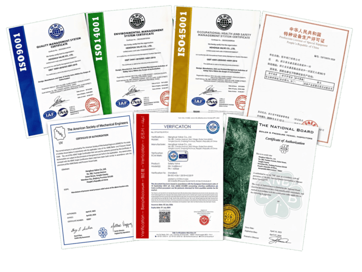
API 2000 or ISO 28300 can be applied as the engineering basis for atmospheric and low-pressure tank venting when required by the project and supported by product data. API 520/526/527 and ASME UV address different pressure-relief contexts and are stated only where they apply to the selected supply.
API 2000 / ISO 28300
Use as sizing/venting basis only where the project and exact HHSV product data support it; state the actual applied edition/basis in the calculation.
Tank design code
The tank/equipment’s allowable positive pressure and vacuum come from its actual design basis and are primary selection inputs.
API 520 / 526 / 527
Check the scope of the proposed standard against the actual device and duty before applying it. These standards are not listed in the current HFA72W product record.
ASME UV
Confirm any required ASME or National Board marking against the exact product and certificate scope. The current HFA72W record does not establish those markings.
Project specification
Owner/EPC requirements for venting, blanketing, emissions, materials, weather protection and inspection may control the supplied configuration.
Certificate matrix
Only claim certification when the exact legal entity, factory, model/range, standard and marking are inside the active certificate scope.
Designed to
State the design and sizing basis applied to the selected HFA72W configuration.
Tested in accordance with
State the actual pressure/vacuum/function/leakage or flow test method recorded for the order.
Certified to
Use only when the exact product configuration and legal scope are covered by the cited authorization/certificate.
Inspection & Functional Testing
Verify the vacuum opening, closing and air-flow requirements for the supplied valve.
Agree the HFA72W opening condition, closing and leakage criteria, required flow evidence and inspection scope for the order. Record the applied test method and acceptance limits with the supplied valve’s identification.
Negative-pressure opening
For HFA72W, verify the vacuum/negative-pressure opening condition and tolerance to the approved test basis.
Vacuum reseating / leakage
Verify return toward the closed condition and leakage criterion at the specified differential.
Air-admission path
Check that the air openings and internal flow path are clear and match the supplied configuration.
Opening and closing action
Verify the valve’s opening and return to the closed condition against the agreed functional test procedure.
Air-Admission Capacity
Provide the agreed air-flow data at the stated negative-pressure differential for the selected size and configuration.
Dimensional / material traceability
Confirm interfaces, critical dimensions, nameplate/flow direction and agreed MTC/PMI/NDT/serial records before release.
Pre-Shipment Visual Verification
Make flow direction, vents and product identity obvious before shipment.
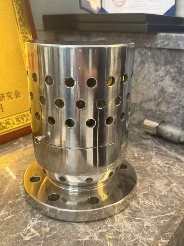
Shipment photos should show the HFA72W nameplate, flange interface, air openings, protective cover and supplied accessories. Compare them with the approved drawing, packing details and inspection records.
Dimensions & Technical Documentation
Receive the selected valve with the calculations, drawings and records required for approval.
Confirm the supplied HFA72W opening condition, air-admission capacity, materials and dimensions through the agreed datasheet, calculation, drawing and test records.
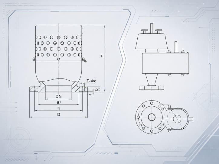
Valve datasheet
HFA72W-10-P/R configuration, service conditions, vacuum opening requirement, materials and flange details.
Vacuum-protection calculation
Vacuum-producing scenarios, vessel pressure limits, required inward air flow and selected capacity basis.
GA / dimension drawing
Overall dimensions, flange interface, installation orientation, cover arrangement and service clearances.
Flow / capacity data
Air-admission capacity at the stated negative-pressure differential for the selected configuration.
Material records
MTC plus agreed PMI/NDT/heat/serial traceability for pressure/wetted components.
Functional test reports
Vacuum opening, closing, leakage and other agreed acceptance records.
QAP / ITP
Inspection stages, hold/witness points, calibration and third-party requirements where contractual.
Quality certificate / final dossier
Controlled document index, approved revisions, certificates/conformity documents and shipment-release records.
Typical Application Routes
Review the vacuum-producing scenario and whether air admission is suitable.
HFA72W selection starts with the vessel’s allowable vacuum, required inward air flow, medium, temperature and material compatibility. Confirm that air admission is permitted and use the selected product’s flow and opening data.
Atmospheric / low-pressure storage tanks
Review the required vacuum-protection function and capacity against the tank’s permitted negative pressure. Assess outward breathing separately.
Oil & chemical storage
Review process compatibility and whether air admission is permitted before selecting vacuum protection for the storage system.
Tank farms & terminals
Liquid withdrawal and cooling can create inward-flow demand. Coordinate the selected vacuum protection with the wider tank vent arrangement.
Process vessels with vacuum risk
HFA72W may be evaluated where cooling, draining or condensation can create unacceptable negative pressure.
Blanketed tanks
Review the blanketing arrangement and whether admitting air is permitted. A vacuum safety valve does not replace the blanketing regulator.
OEM tank / package builders
Standardize the selected vacuum valve, flange interface, drawing and document package after confirming each equipment duty.
Project Requirements
Connect the vessel conditions, vacuum-valve selection and required documents.
Provide the tank or vessel type, permitted vacuum, air-admission requirement and operating conditions. Review the selected HFA72W configuration together with the calculation, drawing and agreed inspection documents.
Tank / equipment
Equipment type, service and project region, with customer confidentiality protected.
Pressure envelope
Normal pressure, allowed positive/vacuum limits, blanketing and vent-header conditions.
Vacuum-protection duty
Withdrawal, cooling or condensation scenarios and the required air-admission capacity.
Delivery Documentation
Approved datasheet/GA, calculation, material records, functional tests and MDR outcome.
FAQ
Vacuum protection and tank-breathing questions
Use the product rating, vacuum opening condition and breathing function as separate selection inputs.
What does HFA72W-10-P/R do?
It opens automatically to admit air when vessel pressure reaches the specified negative-pressure condition. It closes as pressure recovers to the allowable range.
What is the HFA72W-10-P/R product range?
DN15–DN200, 1.0 MPa (PN10), up to 200°C, and flanged connections. The listed media are Air / Corrosive Media. Confirm materials and suitability for the actual service.
Does PN10 specify the vacuum opening setting?
No. PN10 is the nominal pressure rating. The vacuum opening condition and air-admission capacity must be confirmed for the selected valve and equipment duty.
Does HFA72W provide both inward and outward breathing?
HFA72W is described for vacuum protection by air admission. Where the tank also requires outward breathing, select and verify that function separately.
What creates an inbreathing requirement?
Liquid withdrawal, cooling or condensation can reduce vessel pressure. Use the actual operating scenario to establish the required inward air flow and check whether air admission is permitted.
Which standard applies to the selected valve?
The current HFA72W product record does not list a dedicated standard. Agree the applicable design, sizing and test basis for the selected product and project. Certification depends on the exact supplied configuration and certificate scope.
What should I send for a quotation?
Provide the vessel type, normal pressure, allowable vacuum, required air-admission flow or operating scenarios, medium, temperature, flange details, materials and required inspection documents. Include an available vessel drawing or process diagram.
Related Safety Valve Families
Choose the pressure-protection function before choosing the product family.
Spring-Loaded Safety Relief Valves
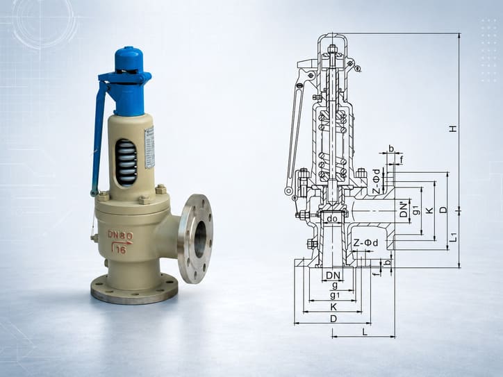
Positive-pressure direct spring-loaded relief family; not a substitute for vacuum/tank-breathing protection.
Pilot-Operated Safety Relief Valves
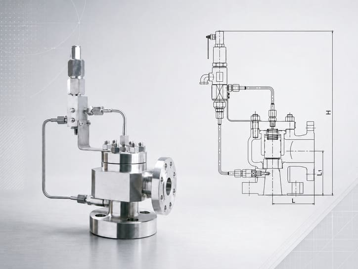
Pilot-controlled positive-pressure relief architecture with its own pressure/capacity data.
Impulse & Main Safety Valve Systems
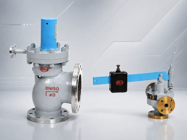
Impulse/main high-capacity steam protection system; a different service and pressure-relief architecture.
All Safety Valves
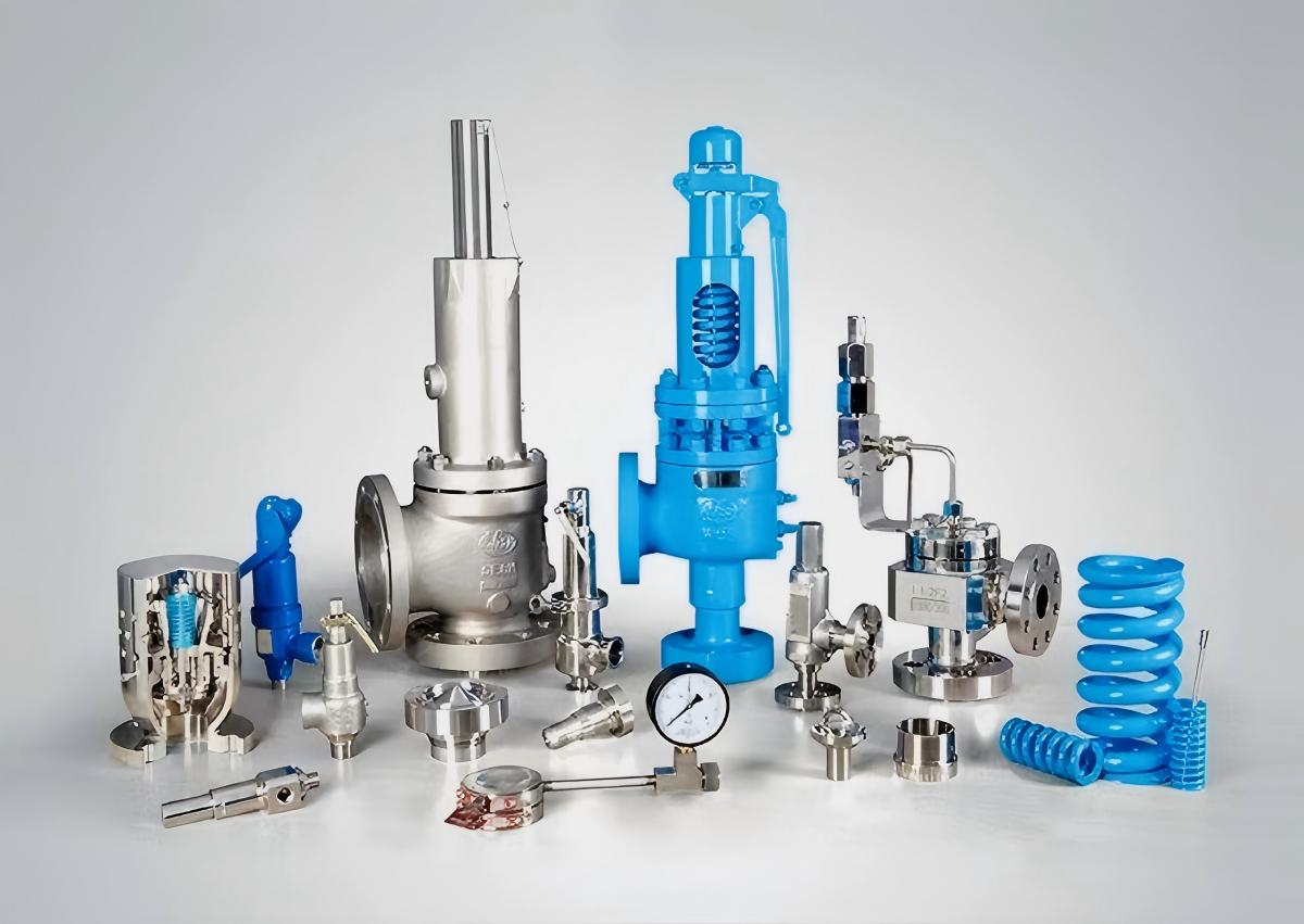
Return to the HHSV family map and select by protection function and real operating data.
Request a Quote
Send the vessel conditions and required vacuum-protection duty.
Provide the allowable vacuum, required inward flow or operating scenarios, medium, temperature, flange details, materials, quantity and required inspection documents. Include an available vessel datasheet or drawing.