
CHANGEOVER & PROCESS ISOLATION
Safety relief accessories & combinations.
HFKH quick crossover devices support safety-valve branch selection. Bursting Disc + Safety Valve combinations provide process isolation upstream of the valve. Select the arrangement around the required relief capacity, service conditions and maintenance plan.
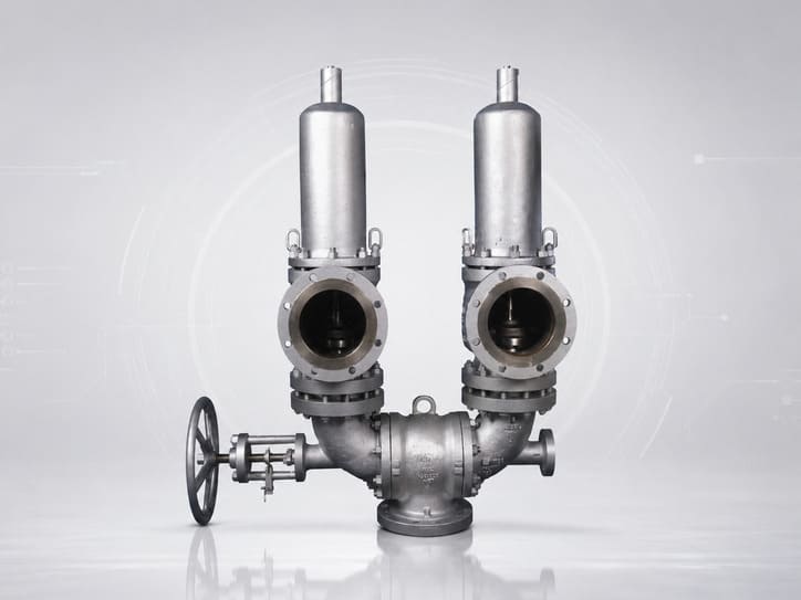
01 · HFKH ACCESSORY
Quick Crossover Device
Gas · Liquid
1–10 in
Class 150–600
-196–540°C
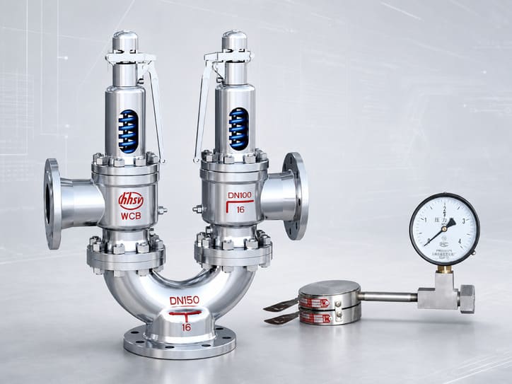
02 · SERIES COMBINATION
Bursting Disc + Safety Valve
Gas · Liquid
1–12 in
0.1–42.0 MPa
150–538°C
System Availability & Protection Layer
Select the safety valve first, then integrate the accessory or combination around the relief duty.
A crossover device routes one protected inlet to an available relief-valve branch. A rupture disc can isolate a safety valve from process fluid until the disc bursts. Neither changes the underlying opening mechanism of the safety valve itself. The selected safety valve still requires its own sizing, code scope, set pressure, materials and certification verification.
Primary relief valve
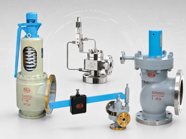
Spring-loaded, pilot-operated or another approved relief-valve family provides the reusable pressure-relief function.
Accessory / switching layer
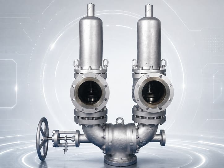
HFKH manages which safety-valve branch is connected to the protected equipment, subject to the approved changeover logic.
Series protection layer
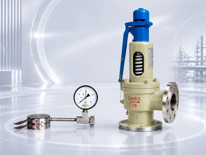
A rupture disc can provide an upstream isolation barrier before the safety valve; the combined assembly must be engineered as one relief path.
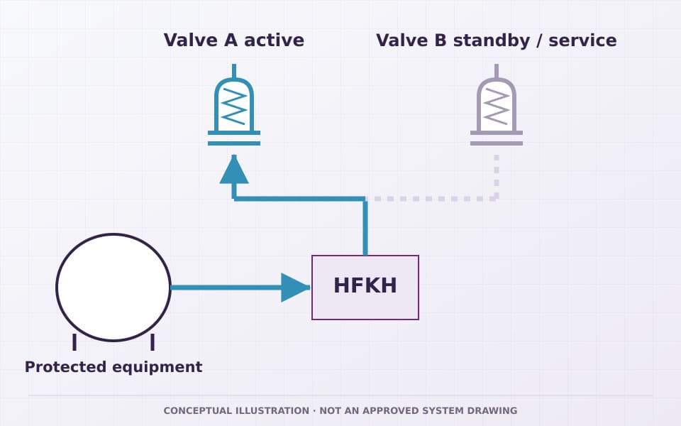
HFKH · Quick Crossover Function
Switch between two relief-valve branches without creating an unprotected closed-both condition.
A quick crossover arrangement allows the protected equipment to be connected to one approved safety-valve branch while the alternate branch is isolated for standby or maintenance. The exact HFKH port geometry, operating sequence, locking/position indication and whether any overlap exists during changeover must follow the current HFKH GA and operating procedure.
01
Protected equipment
One process inlet supplies the relief-protection system.
02
HFKH crossover
The device routes the protected inlet toward the selected relief branch.
03
Valve A active
The selected safety valve must be sized/approved for the required duty when it is the active branch.
04
Valve B standby / service
The alternate branch can be prepared for service or maintenance according to the approved procedure.
05
Controlled changeover
Position and valve availability are verified so the system is never intentionally left without the required relief path.
HFKH Published Specifications
Review the published HFKH range and confirm flow-path, material and connection details.
HFKH is a Safety Valve Quick Crossover Device for gas and liquid service. HHSV confirms the project-specific standard, materials, port and connection schedule, flow-path data, changeover arrangement and operating procedure for the selected configuration.
Medium
Gas · Liquid
published specification
Size
1–10 in
HFKH only
Pressure
Class 150–600
HFKH only
Temperature
-196 to 540°C
HFKH only
Dedicated Standard
Confirm for selected configuration
Verify current datasheet/project basis
Crossover Engineering & Maintenance
Engineer the active and standby branches for continuous, verifiable relief availability.
HHSV engineers the active HFKH branch and connected safety valve to support the full required relief duty. The changeover arrangement maintains the required protection state, while the operating procedure covers authorization, locking, position verification, leak checks and restoration to service.
Full relief path
Confirm HFKH internal passage and the active branch do not reduce the required certified/approved relieving capacity.
No closed-both state
The changeover arrangement/procedure must prevent loss of the required relief path; exact HFKH mechanics are drawing-specific.
Branch maintenance
Isolate only the branch permitted by the approved procedure; depressurize and verify safe condition before removing a valve.
Position Verification
Use position indication, locking/tagging and inspection records appropriate to the project so operators know which branch protects the equipment.
Bursting Disc + Safety Valve Combination
A one-time isolation element upstream of a reusable safety valve changes the whole relief path.
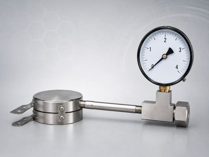
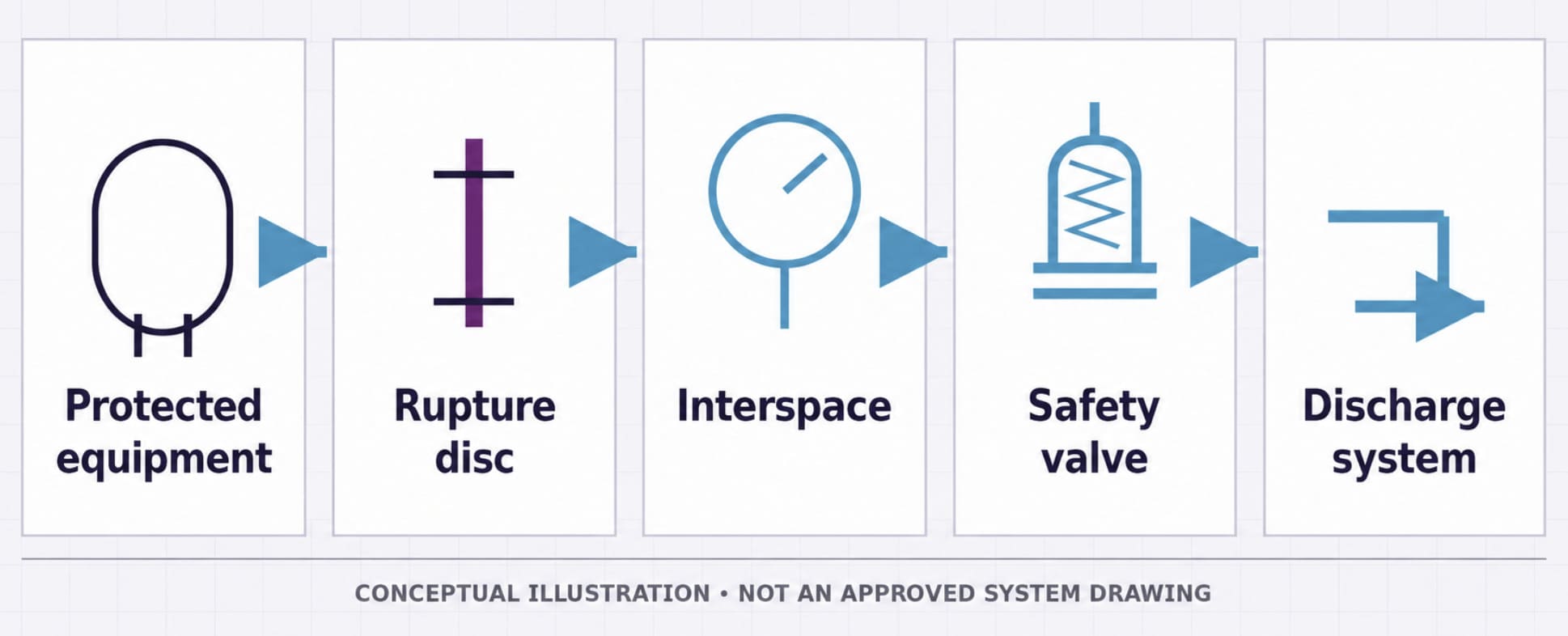
In a common series arrangement, the rupture disc is installed upstream of the safety valve. It can isolate the valve from corrosive, fouling or leak-sensitive process media during normal operation. At the specified overpressure condition the disc ruptures, exposing the safety valve to the relieving flow. The safety valve then provides its normal opening/reseating function. Exact disc location, holder orientation and whether a different arrangement is permitted must follow the approved system drawing and governing code.
01
Protected equipment
Process pressure acts at the inlet of the series relief system.
02
Rupture disc
Normally intact barrier isolates the downstream relief valve from the process until the specified burst condition.
03
Interspace
Pressure between disc and safety valve must be considered and monitored/managed as required by the approved design/code.
04
Safety valve
After disc rupture, the safety valve sees the relieving condition and opens according to its own approved set/function behavior.
05
Discharge system
Combined pressure losses, capacity factor and backpressure must stay within the validated system sizing basis.
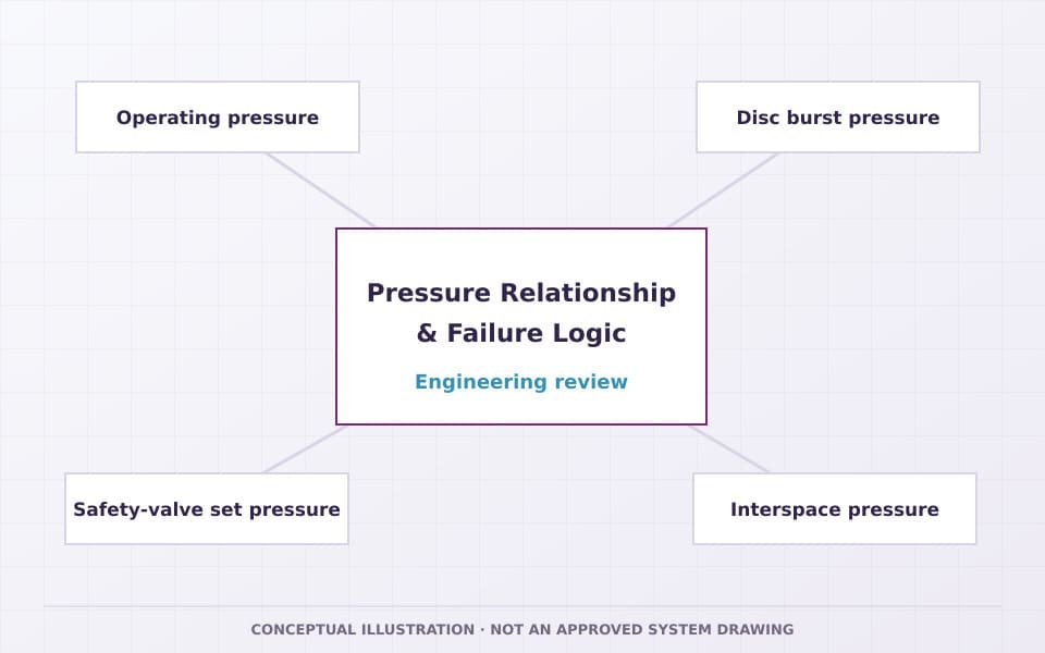
Pressure Relationship & Failure Logic
Burst pressure, safety-valve set pressure and vessel limits must be engineered together.
There is no one safe universal percentage to apply to every rupture-disc/safety-valve combination. The marked burst pressure and tolerance of the disc, the safety-valve set pressure, operating pressure, equipment MAWP/design pressure, accumulation/overpressure allowance, temperature, backpressure and interspace pressure must satisfy the governing code and the tested/approved combination basis.
Operating pressure
Must remain below the limits required for disc stability/fatigue life and below the relief-system set/burst conditions.
Disc burst pressure
Specified at a stated temperature with manufacturing range/tolerance. Do not equate it automatically to the safety-valve set pressure.
Safety-valve set pressure
Belongs to the selected reusable relief valve and applicable code; verify its interaction with upstream disc pressure loss.
Interspace pressure
Pressure trapped or leaked between disc and safety valve can change the effective pressure differential across the disc and must be detected/managed where required.
Combination capacity
Use a tested combination capacity factor or the code-permitted basis applicable to the specific disc + valve pairing; do not use bare-valve capacity automatically.
Fragmentation / opening area
Disc opening behavior, fragment retention and flow area must be compatible with the downstream valve and holder arrangement.
Published Combination Specifications
Apply the published range to the engineered rupture-disc and safety-valve combination.
The published combination range is completed for each project with the rupture-disc type and material, burst-pressure range, holder and connection details, combination capacity factor, interspace monitoring and dimensional schedule.
Medium
Gas · Liquid
published specification
Standard Shown
ASME VIII · API 526
published specification; certification verified separately
Size
1–12 in
Published combination range
Pressure
0.1–42.0 MPa
Published combination range
Temperature
150–538°C
Published combination range
System Sizing & Selection
Size the complete relief path for the governing operating configuration.
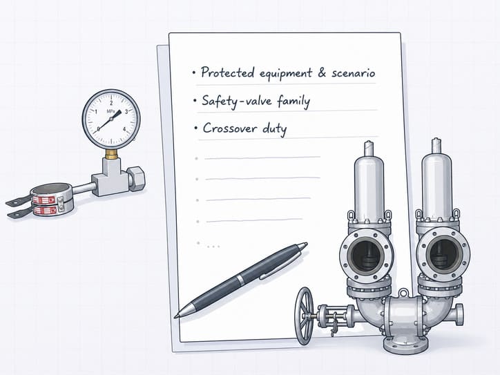
HHSV reviews the complete relief path so the HFKH flow passage, rupture-disc holder and connected piping remain within the approved capacity and pressure-loss basis. The quotation identifies the selected safety-valve family and the role of each accessory.
Protected equipment & scenario
Equipment, credible overpressure case, required capacity, MAWP/design pressure and allowable accumulation.
Safety-valve family
Selected Spring-Loaded / Pilot-Operated / other approved valve, set pressure, orifice/capacity and certificate scope.
Crossover duty
For HFKH: active/standby philosophy, required branch capacity, port arrangement and approved maintenance/changeover state.
Rupture-disc specification
Disc type, marked burst pressure at temperature, tolerance, materials, holder and fragmentation/opening behavior.
Interspace management
Detection, venting/monitoring and acceptable pressure between rupture disc and safety valve.
Pressure losses
Inlet, crossover/disc holder, outlet and backpressure losses at the required relieving flow.
Materials & corrosion
Process chemistry, corrosion, fouling, low/high temperature, MTC/PMI/NDT and compatibility across all system elements.
Connections & layout
Sizes, flange classes/facings, port orientation, changeover access, disc holder orientation and discharge routing.
Code / certification
Applicable pressure equipment code, owner specification, safety-valve marking scope and required combination test evidence.
Inspection & documents
Witness points, position checks, burst-disc certificate, valve test reports, calculations, GA, ITP/MDR and maintenance records.
Materials, Connections & Dimensions
Confirm accessory materials, ports and dimensions for the selected service.
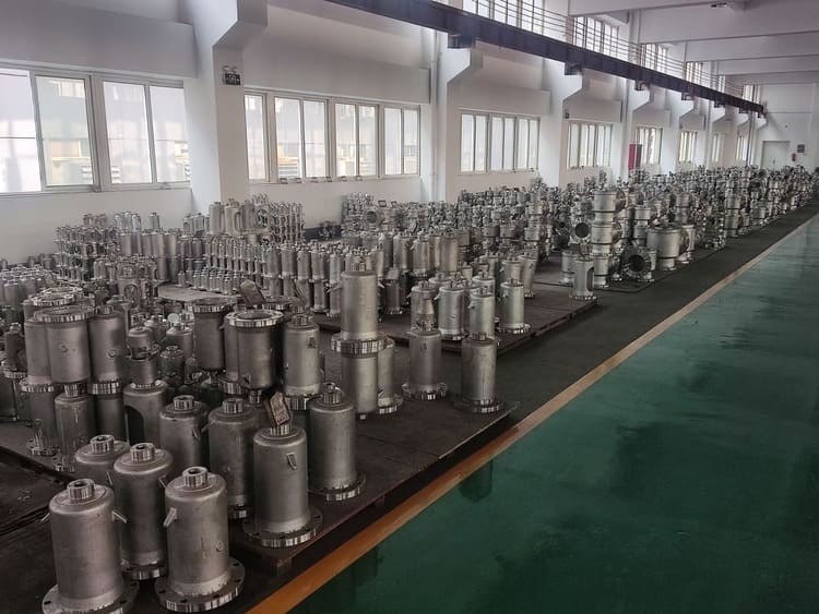
HHSV selects crossover, rupture-disc and holder materials for the medium, corrosion, temperature and project requirements. The controlled BOM, MTC, datasheet and GA confirm flange sizes, facings, port geometry, holder design and dimensions.
HFKH body / internals
Confirm pressure-boundary materials, sealing elements and switching internals by approved BOM and MTC.
Rupture disc / holder
Confirm disc alloy, holder material, orientation, gaskets/seals and compatibility with the selected safety valve.
Connection interfaces
Confirm flange standard/facing, size pairing and rating for every protected-side, branch, holder and valve interface.
GA / dimensional control
Use controlled drawings for port centerlines, envelope, weights, handle/access clearances and disc-holder installation direction.
Standards, Certification & Compliance
Confirm standards and certification for each component and the assembled relief path.
The published combination basis includes ASME Section VIII and API 526. HHSV confirms the applicable design and test basis for the selected safety valve, rupture disc, holder and crossover device. API 520 can support relief-system sizing and installation where specified, while API 527 applies to seat leakage of the selected safety valve.

ASME Section VIII
ASME Section VIII design requirements are confirmed component by component. Any UV or National Board marking applies only to the eligible safety valve within the combination and does not automatically extend to the rupture disc, crossover device or assembled system.
API 526
Shown on the published product data combination record. It is primarily a safety-valve standard and does not by itself define the rupture disc’s burst performance.
API 520
May be an engineering basis for sizing/installation of relief systems and rupture-disc/safety-valve combinations where project/applicable code requires it.
API 527
Use only for seat leakage of the selected safety valve when applicable. It is not the functional test for HFKH or a rupture disc.
HFKH product basis
The quotation states the project-specific pressure-boundary, switching, functional-test and inspection basis for the selected HFKH configuration.
Certificate matrix
Map the actual safety valve, legal entity/factory, model/range, marking and system components before any Certified-to claim.
Designed to
State the design/sizing/installation basis applied to each system component and the combined relief path.
Tested in accordance with
State the actual valve, crossover, rupture-disc and combination tests/acceptance criteria used for the order.
Certified to
Use only when the exact component/product, legal entity, range and marking are within the active authorization/certificate scope.
Inspection, Testing & Functional Verification
Verify component function and the integrity of the complete assembled relief path.
The final ITP should distinguish pressure-boundary tests, crossover switching/position checks, rupture-disc documentation, safety-valve performance tests and combination flow/capacity evidence. Third-party witness points can be added where the project requires them.
HFKH pressure boundary
Verify body/pressure-boundary integrity to the approved pressure and test procedure.
HFKH switching function
Verify travel/position, permitted changeover sequence, leakage/isolation behavior and position indication required by the approved design.
Active-branch flow path
Confirm the selected HFKH position presents the required open path to the safety valve and that interfaces match the approved GA.
Rupture-disc certificate
Verify disc tag, marked burst pressure at temperature, manufacturing range/tolerance, material and lot/serial traceability.
Combination performance
Use required combination capacity/flow evidence and verify disc-to-valve compatibility under the governing code/project basis.
Safety-valve test
Set pressure, reseating/blowdown and seat leakage tests remain specific to the selected relief valve and applicable standard.
Maintenance & Lifecycle Control
Switching hardware and rupture discs require different maintenance logic.
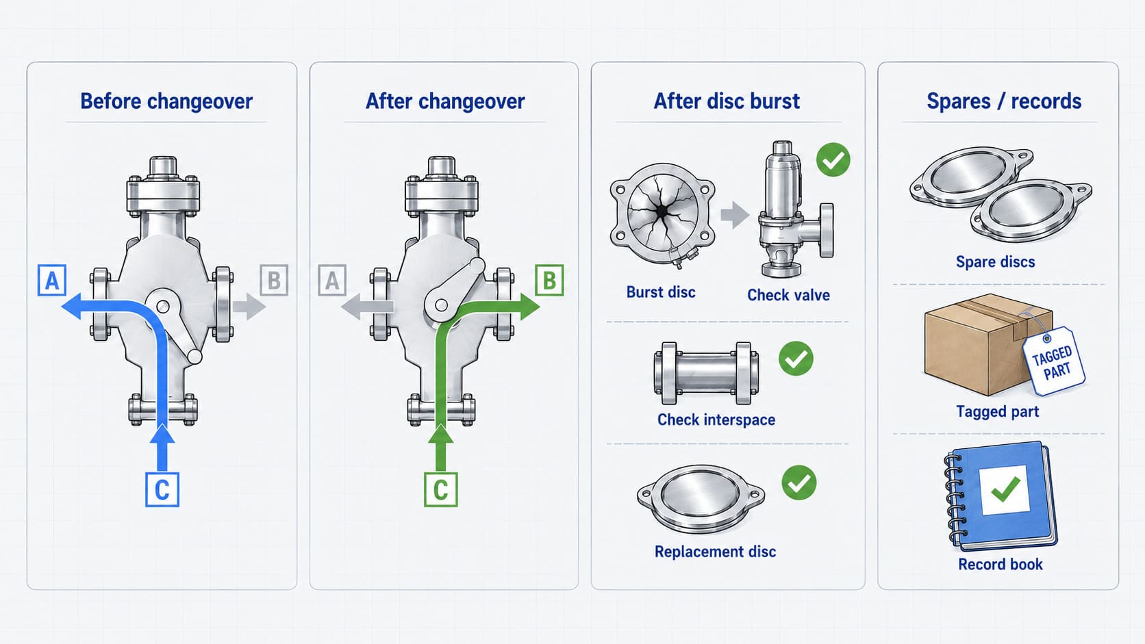
HFKH is a reusable switching/accessory device and should be inspected for position, sealing, operation and branch availability under the site procedure. A rupture disc is a one-time pressure-relief element: after bursting it must be replaced with the correct tagged specification, and the safety valve/interspace should be inspected for process ingress, debris or abnormal pressure before return to service.
Before changeover
Verify alternate valve status, correct setting/certification, isolation condition and approved operator authorization.
After changeover
Confirm the required branch is fully connected, position is recorded/secured and the relief path has not been unintentionally restricted.
After disc burst
Replace the disc with the exact approved specification and inspect the safety valve, holder and interspace before recommissioning.
Spares / records
Control rupture-disc lots/tags, crossover seals/parts, safety-valve spares, calibration/test records and maintenance history.
Technical Documentation
The accessory only becomes useful when the whole relief path is visible in the documents.
The submittal should make valve identity, branch routing, rupture-disc specification, pressure relationships, tested capacity basis and maintenance/changeover instructions auditable. Model-level claims come from controlled drawings/data, not from the family page.
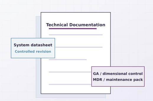
System datasheet
Protected equipment, selected safety-valve family, accessory/combination arrangement and pressure/temperature basis.
Relief sizing calculation
Credible case, required capacity, pressure losses and applicable HFKH/rupture-disc combination factors.
HFKH GA / port drawing
Port function, position, connection sizes, dimensions, handle/access clearances and active-branch identification.
Rupture-disc datasheet
Disc type, marked burst pressure/temperature, tolerance, material, holder and orientation.
Combination GA / P&ID
Protected inlet, disc/holder, interspace monitoring, safety valve and discharge system arrangement.
Material / traceability records
MTC plus specified PMI/NDT/lot/serial records for crossover, holder, disc and safety-valve scope.
Inspection / test reports
HFKH switching checks, rupture-disc certificates, safety-valve test reports and combination performance documentation are supplied as applicable.
MDR / maintenance pack
Approved revisions, certificate matrix, ITP, position/changeover instructions, spares and final release records.
Where These System Layers Add Value
Use an accessory or combination only when it solves a defined availability or process-isolation problem.
Selection still starts from the actual safety valve and relieving scenario. The accessory/combination is justified by maintenance strategy, process cleanliness/corrosion, leakage control, service continuity, code rules and the ability to verify the complete relief path.
Maintenance-sensitive equipment
HFKH can support a dual-branch philosophy where one approved valve branch must remain available while the alternate branch is serviced.
Corrosive / fouling service
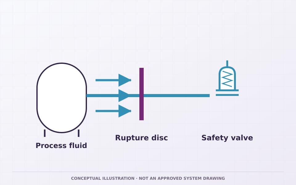
An upstream rupture disc may isolate the safety valve from process exposure until the relief event, subject to material and combination validation.
Leak-sensitive process
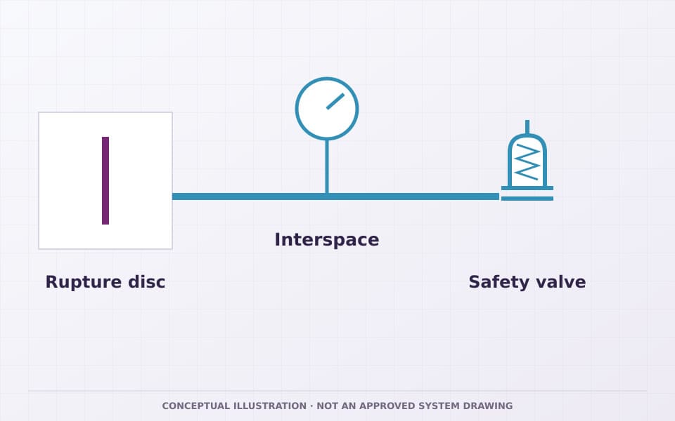
A rupture disc can add a sealed barrier upstream of the safety valve where fugitive process leakage through the valve seat is unacceptable.
Recurring inspection programs
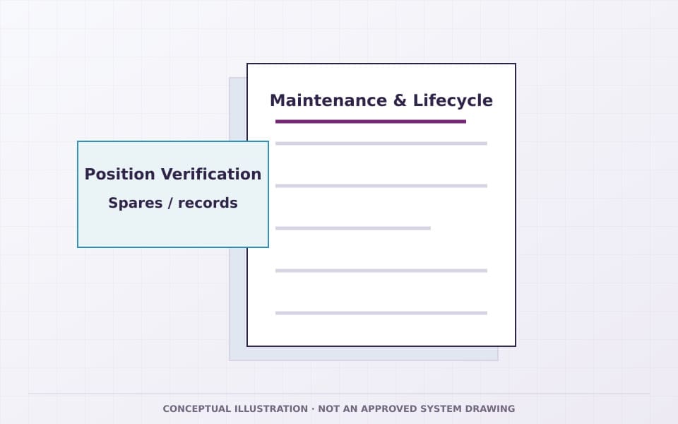
A controlled crossover arrangement can help plan valve servicing where the governing code/site procedure permits online changeover.
Engineered pressure systems
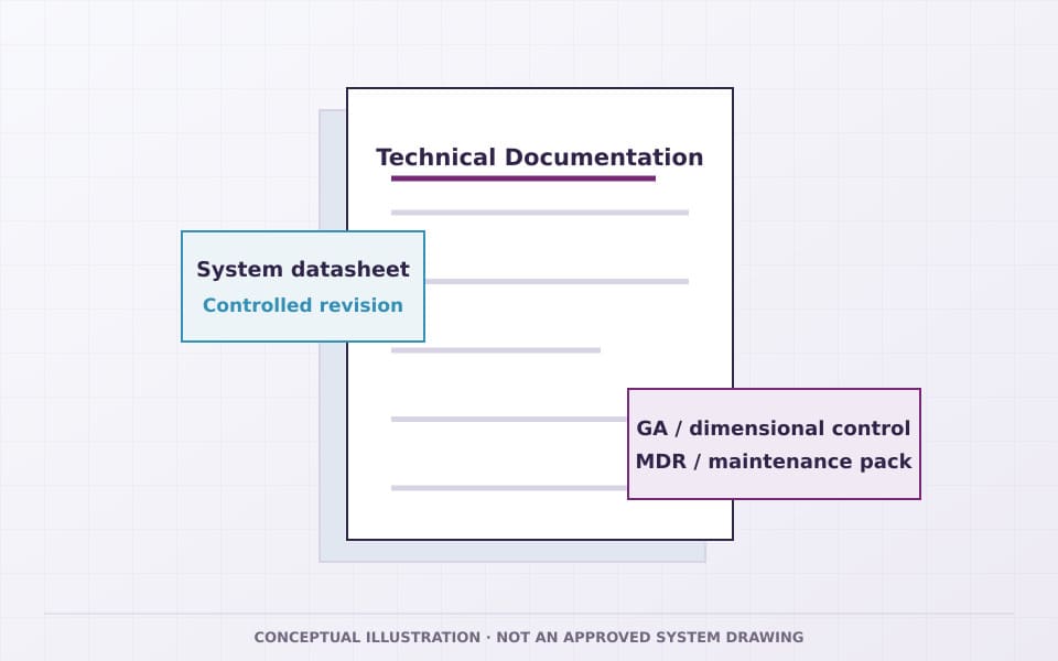
EPC/OEM projects can freeze one approved system GA, valve/disc/accessory BOM, test plan and maintenance procedure for repeat builds.
Engineering value
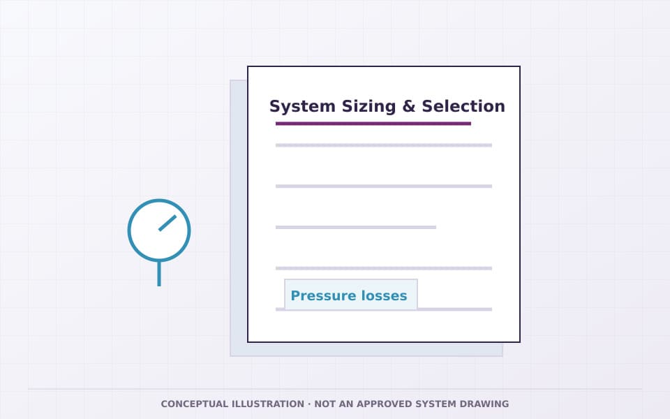
Neither HFKH nor a rupture disc combination compensates for an undersized, incorrectly set or uncertified safety valve.
FAQ
Accessory and combination questions
Clear Technical Boundaries for Accessories, Combinations and the Primary Relief Valve.
Is HFKH a safety valve?
No. HHSV's published product data calls HFKH a Safety Valve Quick Crossover Device. It is a system/accessory component that routes the protected inlet to a selected safety-valve branch. The active safety valve still provides the pressure-relief function.
Can HFKH let me service one safety valve without shutting down the equipment?
Potentially, when the approved system design, governing code and site procedure allow it. The active branch must provide the required relief protection, and the changeover arrangement must not leave both required relief paths isolated. Exact HFKH positions and operating sequence come from the approved GA/instructions.
What is the published HFKH range?
The published product data lists gas and liquid, 1–10 in, Class 150–600 and -196–540°C. It does not publish a dedicated standard, material/port matrix or flow-area table in this record.
Why install a rupture disc upstream of a safety valve?
A rupture disc can isolate the safety valve from process media during normal operation, which may help with corrosion, fouling or leak-sensitive service. At the specified burst condition the disc opens and the safety valve provides the reusable relief function. The complete series path must be sized and validated as a combination.
Should rupture-disc burst pressure equal safety-valve set pressure?
Do not assume one universal relationship or percentage. Disc burst pressure/tolerance at temperature, safety-valve set pressure, equipment MAWP/design pressure, operating pressure, accumulation and interspace pressure must satisfy the governing code and the tested/approved system basis.
Why monitor the space between a rupture disc and safety valve?
Pressure in the interspace can change the differential pressure acting on the rupture disc and can also indicate leakage or disc damage. Monitoring/venting requirements depend on the governing code and approved system design.
Does ASME VIII / API 526 on the published product data mean the entire combination is automatically certified?
No. Those standards are shown on the published product data combination record, but certification/marking claims must be verified for the exact safety valve, rupture disc/holder, legal entity, model/range and assembled system scope.
What should I send for an RFQ?
Send the protected equipment, required relieving capacity, operating/set pressure, temperature, medium, backpressure, selected or required safety-valve family, HFKH changeover philosophy or rupture-disc purpose, connection/material requirements, code/certification, P&ID/GA, inspection/document scope and delivery target.
Related Safety Valve Families
Return to the relief valve that provides the protective opening function.
Spring-Loaded Safety Relief Valves
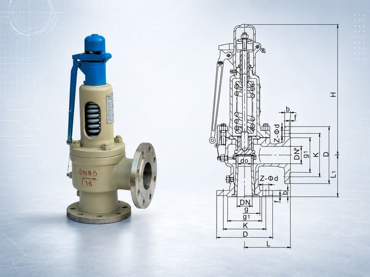
Direct spring-loaded safety valves for pressure-relief duties. Compare the selected model’s medium, operating range and connections.
Pilot-Operated Safety Relief Valves
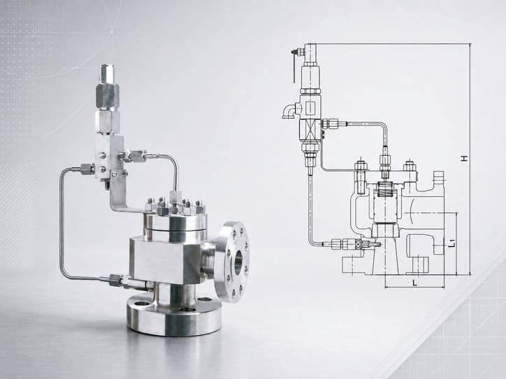
A46 pilot-operated safety valves in PN16/25/40 and PN64/100/160 groups. Select the pressure group, size and configuration for the relief duty.
Impulse & Main Safety Valve Systems
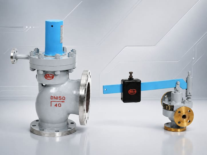
A49H-40 main safety valves with GA49H-4.0 DN25 impulse valves for steam service. The impulse valve initiates opening; the main valve releases steam.
All Safety Valves
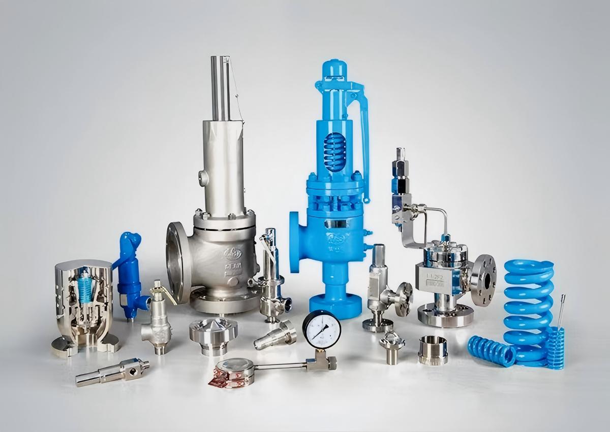
Select the Safety-Valve Family that Provides the Primary Relief Function.
Request a Quote
Send the relief case and maintenance/isolation objective - HHSV will define the accessory system around the safety valve.
Provide medium, capacity, operating/set pressure, temperature, backpressure, selected safety-valve family, HFKH changeover or rupture-disc objective, connections, materials, standards/certification, P&ID/GA, inspection, documents, quantity and delivery target.